Resonant coil for measuring specimen condition

a coil and specimen technology, applied in the field of conductivity measurements, can solve the problems of confusing measurement interpretation, less straightforward interpretation, and use of coil related parameters by either expensive or awkward instruments

Inactive Publication Date: 2014-05-13
KIMBERLY-CLARK WORLDWIDE INC
View PDF22 Cites 7 Cited by
  • Summary
  • Abstract
  • Description
  • Claims
  • Application Information

AI Technical Summary

Benefits of technology

[0005]A noninvasive induction type sensor measures electrical conductivity at some depth beneath the skin, and without the usual attachment of electrodes to the skin surface. In one embodiment, an induction coil forms part of an RLC auto-resonant circuit that is forced to remain in resonance by a varactor diode combined with phase-locked loop circuitry. With such an arrangement, impedance of the resonant circuit and thus tissue conductivity is straightforward to measure, leading to compact electronics. A number of applications are contemplated, including an ability to monitor recovery from hypothermia, onset of hyperthermia, impairment of blood circulation or other circulator performance, cardiovascular elasticity, cardiac output, arterial dilation, edema, and fat distribution.

Problems solved by technology

In spite of techniques employed to date, various technical issues prevent widespread use: not well known or understood; competing invasive methods; inadequate development of models to distinguish the variety of factors contributing to human tissue conductivity, making interpretation less straightforward; and use of either expensive or awkward instrumentation to measure coil related parameters such as complex impedance.
Such an arrangement makes interpretation of measurements more confusing.

Method used


Image

  • Resonant coil for measuring specimen condition
  • Resonant coil for measuring specimen condition
  • Resonant coil for measuring specimen condition

Examples


Embodiment Construction

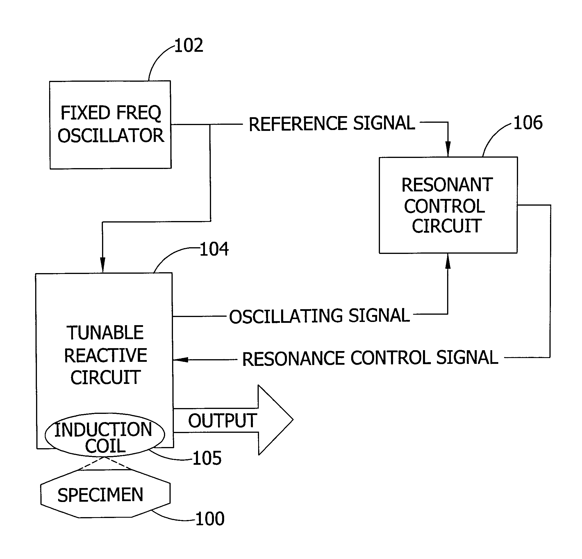
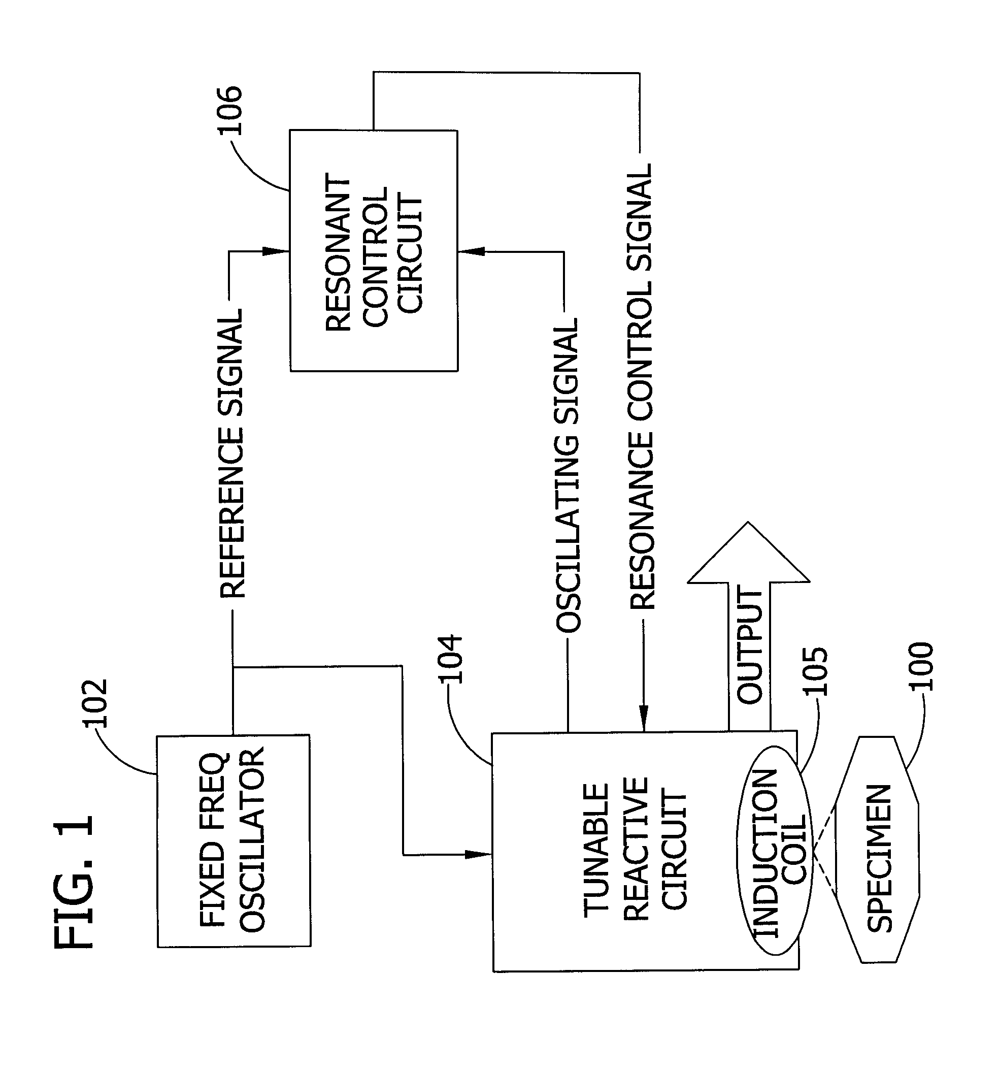
[0013]In one form, the invention comprises an apparatus for measuring a condition (e.g., conductivity) of a specimen 100, such as human tissue, as illustrated in FIG. 1. A fixed frequency oscillator 102 provides a fixed frequency reference signal having a phase. An induction coil of a tunable reactive circuit 104, such as a series RLC circuit, is driven by the reference signal of the oscillator 102. The fixed frequency oscillator 102 is independent of and isolated from the tunable reactive circuit 104. The circuit 104 includes an induction coil 105 adapted to be positioned adjacent the specimen 100. The circuit 104 generates an oscillating signal corresponding to the condition of the specimen 100. In other words, the proximity of the specimen 100 to circuit 104 affects the point of resonance of the reactive circuit, such as by modifying the impedance of the reactive circuit.

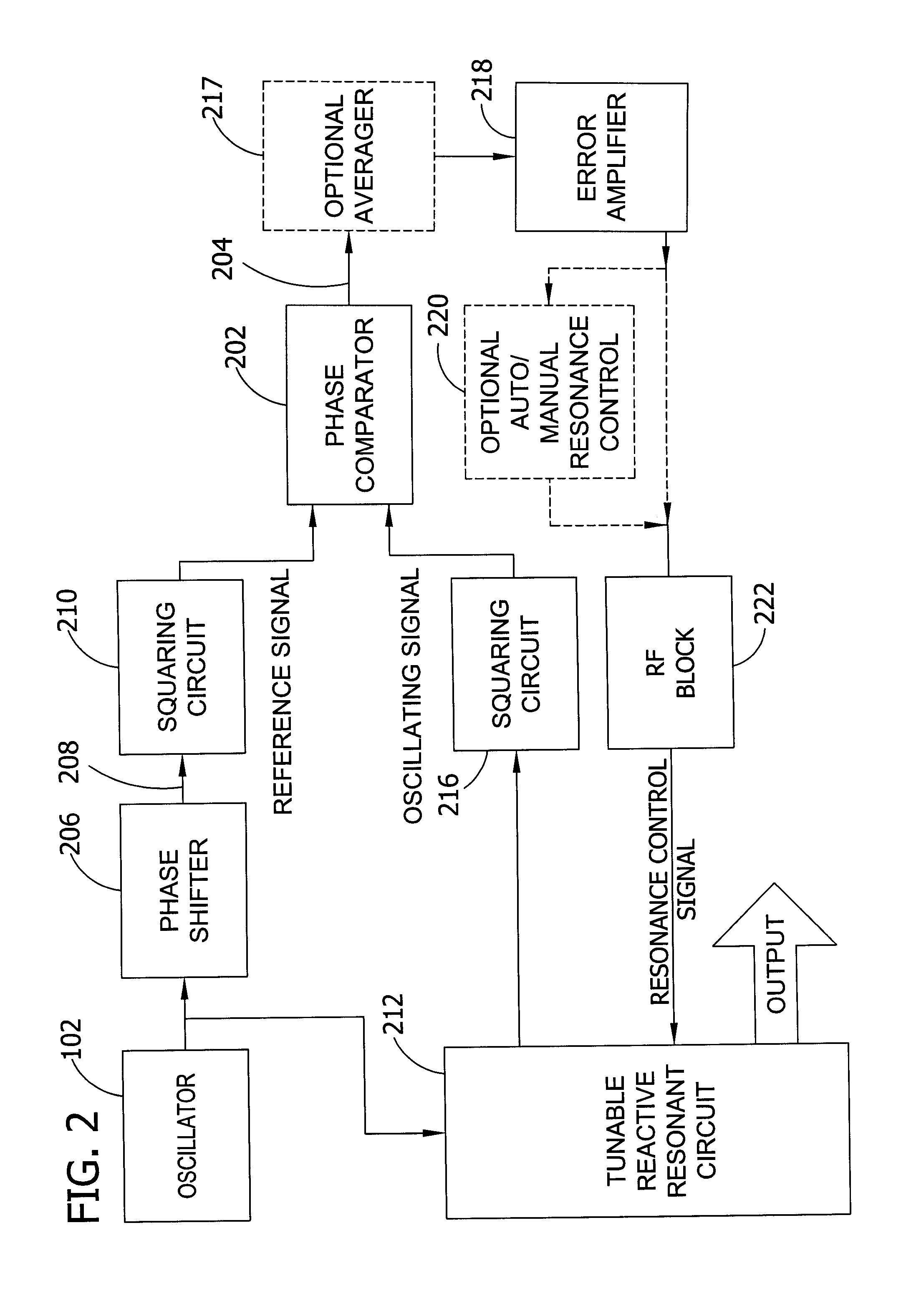
[0014]A resonant control circuit 106 compares the reference signal to the oscillating excitation signal and pr...


PUM


Abstract

An oscillator provides a reference signal having a phase. A tunable reactive circuit, including an induction coil, is driven by the fixed frequency reference signal of the oscillator with coil adapted to be positioned adjacent the specimen to generate an oscillating signal corresponding to the condition of the specimen. The tunable reactive circuit provides an output signal having a parameter indicative of the condition of the specimen. A resonant control circuit compares the reference signal to the oscillating signal and provides to the tunable reactive circuit a resonance control signal representative of the comparison. The resonance control signal tunes the tunable reactive circuit, which may be a series RLC circuit, so that the frequency of the oscillating signal is substantially constant.

Description

FIELD OF THE INVENTION[0001]The present invention generally relates to conductivity measurements and, in particular, determining a condition of a specimen by noninvasive measurement of its conductivity.BACKGROUND OF THE INVENTION[0002]Measurement of conductivity for most liquids or solids involves the use of electrodes which are placed into contact with the specimen of interest. A voltage is applied (usually AC) with resulting current measured and conductivity computed. In some cases, many electrodes are attached so that a kind of imaging is made possible, provided that conductivity varies spatially through the specimen. This latter condition is true for geological specimens and human tissue specimens.[0003]An alternative is to generate eddy currents within the specimen through inductive coupling to an external coil. The eddy currents exist in proportion to the local conductivity of the material and can be detected in a number of ways. A recent technique in connection with attemptin...

Claims


Application Information

Patent Timeline
Patent Type & Authority Patents(United States)
IPC IPC(8): G01R27/08A61B5/05
CPCA61B5/053A61B5/4872A61B5/0537G01H13/00
Inventor FELDKAMP, JOSEPH R.HELLER, JEFFREY R.SULLIVAN, SHAWN J.
Owner KIMBERLY-CLARK WORLDWIDE INC
Why Eureka
Try Eureka