High-strength veneer tie and thermally isolated anchoring systems utilizing the same

a veneer tie and anchoring system technology, applied in the direction of shock-proofing, building components, covering/lining, etc., can solve the problems of insufficient insulation integrity of the system, frequent failure of the anchoring system, and hampered installation, so as to increase the strength of the veneer tie

Active Publication Date: 2014-05-20
HOHMANN & BARNARD INC
View PDF87 Cites 33 Cited by
  • Summary
  • Abstract
  • Description
  • Claims
  • Application Information

AI Technical Summary

Benefits of technology

[0044]The veneer tie is positioned so the patterned insertion end thereof is embedded in the outer wythe bed joint. The construction of the veneer tie results in an orientation upon emplacement so that the widest part of the interconnecting portion is subjected to the compressive and tensile forces. The driver portion of the anchor contains an oval aperture with predetermined dimensions to accept the veneer tie and restrict the movement of the construct, preventing veneer tie pullout.
[0056]It is another feature that the close control of the overall height of the veneer tie insertion portion permits the mortar of the bed joints to flow over and about the veneer ties.

Problems solved by technology

Prior tests have shown that failure of anchoring systems frequently occurs at the juncture between the veneer tie and the receptor portion of the wall anchor.
However, under certain conditions, the system did not sufficiently maintain the integrity of the insulation.
Besides earthquake protection, the failure of several high-rise buildings to withstand wind and other lateral forces resulted in the incorporation of a continuous wire reinforcement requirement in the Uniform Building Code provisions.
In general, the pintle-receiving sheetmetal version of the Seismiclip® interlock system served well, but in addition to the insulation integrity problem, installations were hampered by mortar buildup interfering with pintle leg insertion.
Upon experiencing lateral forces over time, this resulted in the loosening of the stud.
Contractors found that heavy wire anchors, with diameters approaching the mortar layer height specification, frequently result in misalignment.
However, the above-described technology did not fully address the adaption thereof to insulated inner wythes utilizing stabilized stud-type devices.
However, as there is no thermal break or barrier, a concomitant loss of the insulative integrity results.
Although steel offers many benefits, it does not provide the high insulation efficiency of timber framing and can cause the effective R-value of fiberglass batt insulation between the steel studs to fall 50 to 60%.
While the gapping was largely resolved by placing a self-sealing, dual-barrier polymeric membrane at the site of the legs and the mounting hardware, with increasing thickness in insulation, this patchwork became less desirable.

Method used


Image

  • High-strength veneer tie and thermally isolated anchoring systems utilizing the same
  • High-strength veneer tie and thermally isolated anchoring systems utilizing the same
  • High-strength veneer tie and thermally isolated anchoring systems utilizing the same

Examples


first embodiment

[0076]The description which follows is of three embodiments of anchoring systems utilizing the high-strength ribbon veneer tie devices of this invention, which devices are suitable for nonseismic and seismic cavity wall applications. Although each high-strength veneer tie is adaptable to varied inner wythe structures, the embodiments here apply to cavity walls with insulated masonry inner wythes, and to cavity walls with insulated and uninsulated dry wall (sheetrock) inner wythes. The wall anchor of the first embodiment is adapted from that shown in U.S. Pat. No. 8,037,653 of the inventors hereof.

[0077]In accordance, with the Building Code Requirements for Masonry Structures, ACI 530-05 / ASCE 5-05 / TMS 402-05, Chapter 6, each wythe of the cavity wall structure is designed to resist individually the effects of the loads imposed thereupon. Further, the veneer (outer wythe) is designed and detailed to accommodate differential movement and to distribute all external applied loads through ...

second embodiment

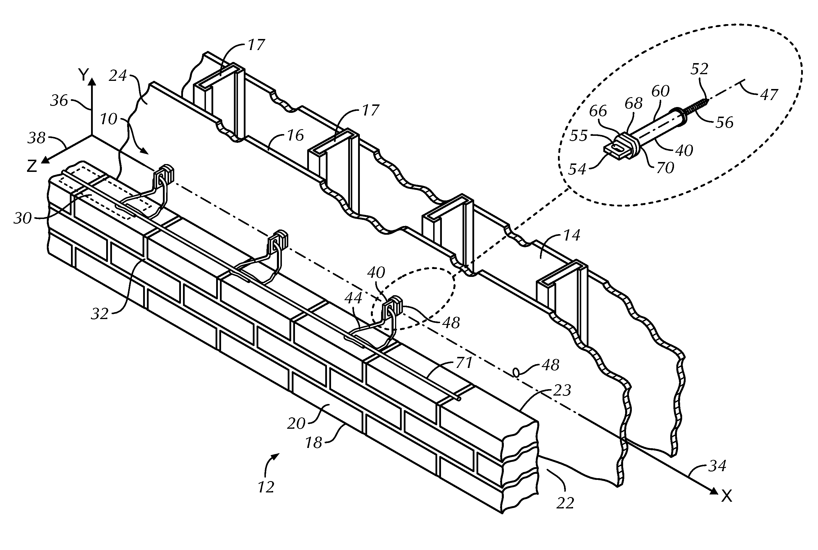
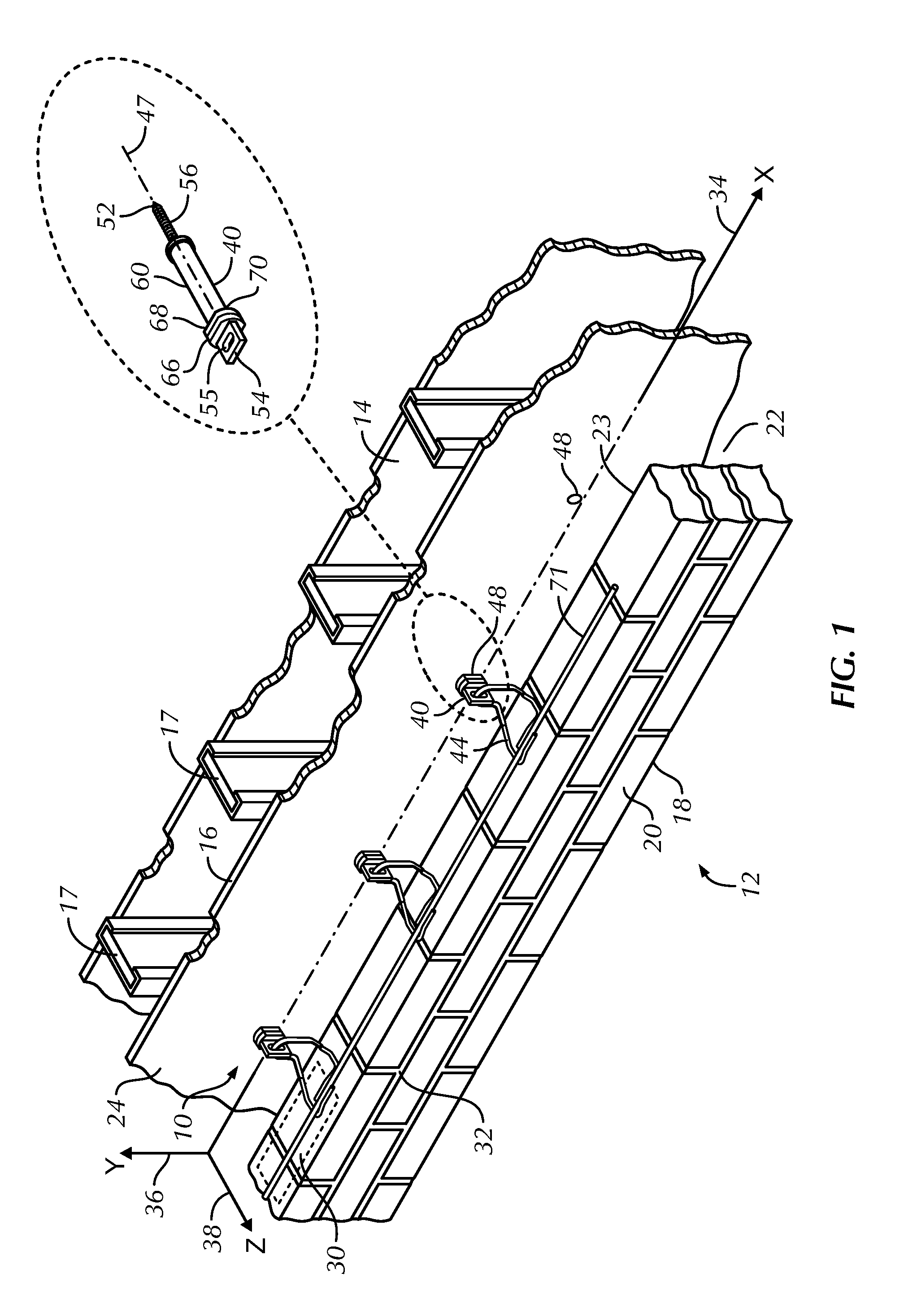
[0094]Referring now to FIGS. 2 through 8 and 13, the anchoring system is shown and is referred to generally by the number 110. A cavity wall structure 112 is shown having an inner wythe or masonry backup 114 with rigid insulation thereon 126 and an outer wythe or veneer 118 of brick 120 construction. Between the inner wythe 114 and the outer wythe 118, a cavity 122 is formed. The outer wythe 118 has a facial plane in the cavity 122.

[0095]Successive bed joints 130 and 132 are substantially planar and horizontally disposed in the outer wythe 118 and, in accord with current building standards, are 0.375-inch (approx.) in height. Selective ones of bed joints 130 and 132, which are formed between courses of bricks 120, are constructed to receive therewithin the insertion portion of the veneer anchor hereof. Being threadedly mounted in the inner wythe, the wall anchor is supported thereby and, as described in greater detail herein below, is configured to minimize air and moisture penetrat...


PUM


Abstract

An anchoring system for cavity walls is disclosed and includes a wall anchor and a high-strength veneer tie. The anchor includes nonconductive thermally-isolating components that maintain the insulation R-values. The anchor features seals located at insertion points in the layers of the interior wythe that stabilize the wall anchor and protect against the entry of liquids and vapor. The veneer tie utilizes a ribbon connector that is cold-worked with the resultant body having substantially semicircular edges and flat surfaces therebetween. The edges are aligned to receive compressive forces transmitted from the outer wythe. The veneer tie, when part of the anchoring system, interengages with the wall anchor and is dimensioned to preclude significant veneer tie movement and to preclude pullout.

Description

BACKGROUND OF THE INVENTION[0001]1. Field of the Invention[0002]This invention relates to an improved anchoring arrangement for use in conjunction with cavity walls. More particularly, the invention relates to construction accessory devices, namely, veneer ties with a compressed interconnection junction and a thermally isolated sealing anchoring system for insulated cavity walls. The invention is applicable to structures having an outer wythe of brick or stone facing in combination with an inner wythe of either masonry block or dry wall construction with optional insulation thereon.[0003]2. Description of the Prior Art[0004]In the past, investigations relating to the effects of various forces, particularly lateral forces, upon brick veneer masonry construction demonstrated the advantages of having high-strength wire anchoring components embedded in the bed joints of anchored veneer walls, such as facing brick or stone veneer. Anchors and ties are generally placed in one of the follo...

Claims


Application Information

Patent Timeline
Patent Type & Authority Patents(United States)
IPC IPC(8): E04B1/16
CPCE04B1/41E04B1/98E04B1/38E04F13/0805E04F13/0821E04B1/7616E04B1/4178
Inventor HOHMANN, JR., RONALD, P.
Owner HOHMANN & BARNARD INC
Why Eureka
Try Eureka