High-strength vertically compressed veneer tie anchoring systems utilizing and the same

a vertical compression and anchoring system technology, applied in the direction of walls, building components, structural elements, etc., can solve the problems of insufficient insulation integrity of the system, frequent failure of the anchoring system, and hampered installations, etc., to achieve high insulation value, reduce the risk of harmed installations, and reduce the effect of tensile for

Inactive Publication Date: 2014-12-09
HOHMANN & BARNARD INC
View PDF206 Cites 20 Cited by
  • Summary
  • Abstract
  • Description
  • Claims
  • Application Information

AI Technical Summary

Benefits of technology

[0036]It is another object of the present invention to provide labor-saving devices to simplify seismic and nonseismic high-strength installations of brick and stone veneer and the securement thereof to an inner wythe.
[0037]It is yet another object of the present invention to provide a cold worked wire formative veneer tie that is characterized by high resistance to compressive and tensile forces.
[0038]It is another object of the present invention to prevent air infiltrati

Problems solved by technology

Prior tests have shown that failure of anchoring systems frequently occurs at the portion of the veneer tie that lies within the cavity.
The prior art veneer tie cavity sections often retain stray mortar and moisture within the cavity.
However, under certain conditions, the system did not sufficiently maintain the integrity of the insulation.
Besides earthquake protection, the failure of several high-rise buildings to withstand wind and other lateral forces resulted in the incorporation of a continuous wire reinforcement requirement in the building code provisions.
In general, the pintle-receiving sheetmetal version of the Seismiclip® interlock system served well, but in addition to the insulation in

Method used


Image

  • High-strength vertically compressed veneer tie anchoring systems utilizing and the same
  • High-strength vertically compressed veneer tie anchoring systems utilizing and the same
  • High-strength vertically compressed veneer tie anchoring systems utilizing and the same

Examples


first embodiment

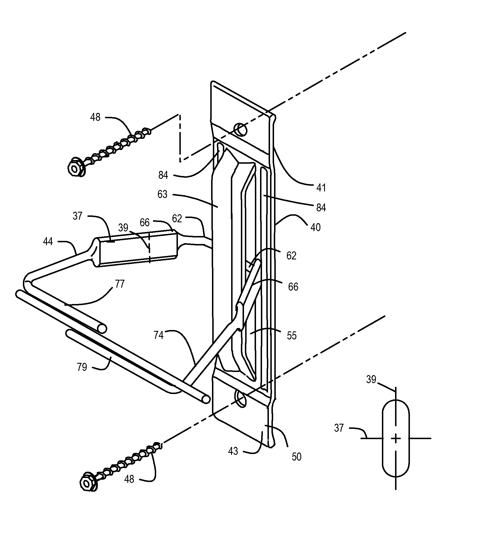
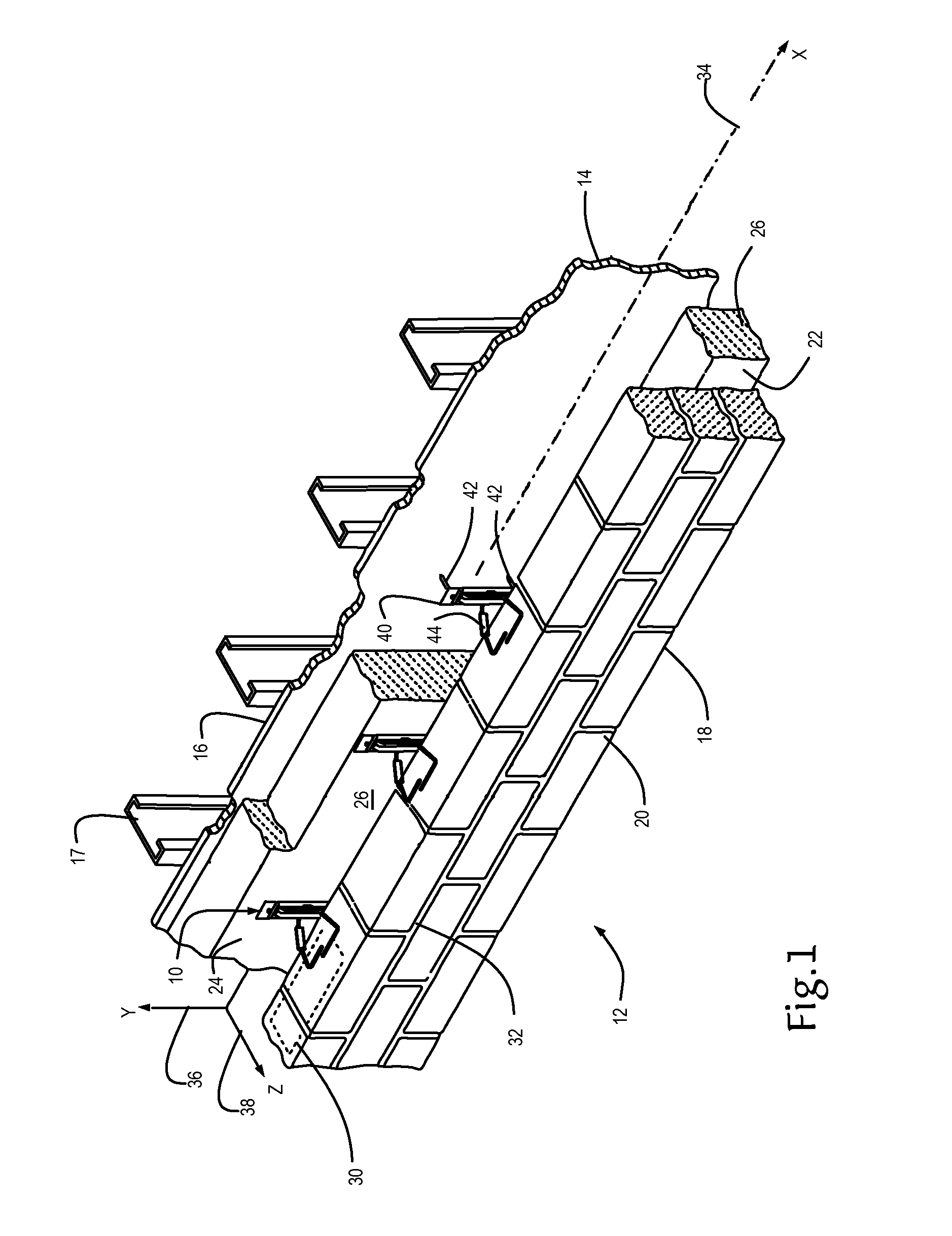
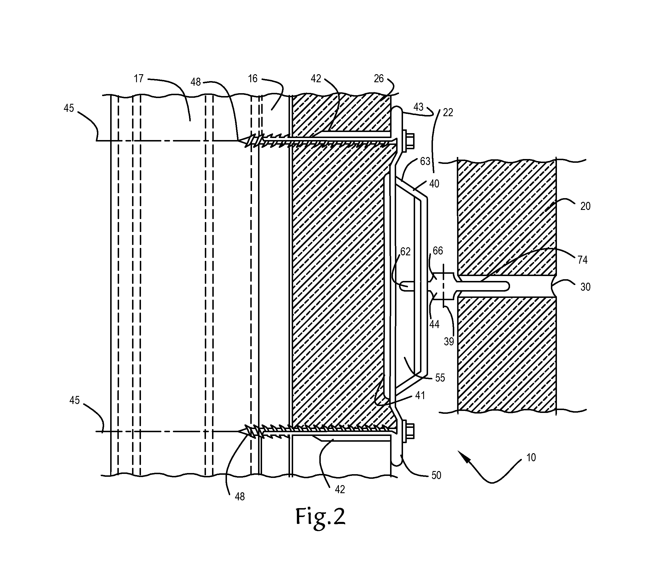
[0063]Referring now to FIGS. 1 through 5, and 10, the anchoring system hereof including a high-strength vertically compressed or ribbon veneer tie of this invention is shown and is referred to generally by the number 10. A cavity wall structure 12 is shown having an inner wythe or drywall backup 14 with sheetrock or wallboard 16 mounted on metal framing members or columns 17 and an outer wythe or facing wall 18 of brick 20 construction. Inner wythes constructed of masonry materials or wood framing are also applicable. Between the inner wythe 14 and the outer wythe 18, a cavity 22 is formed. The outer wythe 18 has a facial plane or cavity surface 24 in the cavity 22.

[0064]Successive bed joints 30 and 32 are substantially planar and horizontally disposed and, in accord with current building standards, are 0.375-inch (approx.) in height. Selective ones of bed joints 30 and 32, which are formed between courses of bricks 20, are constructed to receive therewithin the insertion portion of...

second embodiment

[0074]Referring now to FIGS. 6 through 10, the anchoring system is shown and is referred to generally by the number 110. A cavity wall structure 112 is shown having an inner wythe or masonry backup 114 with rigid insulation thereon 126 and an outer wythe or veneer 118 of brick 120 construction. Between the inner wythe 114 and the outer wythe 118, a cavity 122 is formed. The outer wythe 118 has a facial plane or cavity surface 124 in the cavity 122.

[0075]Successive bed joints 130 and 132 are substantially planar and horizontally disposed in the outer wythe 118 and, in accord with current building standards, are 0.375-inch (approx.) in height. Selective ones of bed joints 130 and 132, which are formed between courses of bricks 120, are constructed to receive therewithin the insertion portion of the veneer anchor hereof. Being surface mounted in the inner wythe 114, the wall anchor 140 is supported thereby and, as described in greater detail herein below, is configured to minimize air ...


PUM


Abstract

An anchoring system for cavity walls is disclosed and includes a wall anchor and a high-strength partially compressed veneer tie. The anchor preserves the insulation integrity by sealing the insertion points in the inner wythe. The veneer tie utilizes ribbon cavity portions that are cold-worked and vertically compressed, with the resultant body having substantially semicircular edges and flat surfaces therebetween. The edges are aligned to receive compressive forces transmitted from the outer wythe. The veneer tie, when part of the anchoring system, interengages with the wall anchor and is dimensioned to preclude significant veneer tie movement, preclude pullout and shed moisture and mortar within the cavity.

Description

BACKGROUND OF THE INVENTION[0001]1. Field of the Invention[0002]This invention relates to an improved anchoring arrangement for use in conjunction with cavity walls. More particularly, the invention relates to construction accessory devices, namely, veneer ties with vertically compressed cavity portions, and a sealing anchoring system for insulated cavity walls. The invention is applicable to structures having an outer wythe of brick or stone facing in combination with an inner wythe of either masonry block or dry wall construction. The system has application to non-seismic and seismic-resistant structures.[0003]2. Description of the Prior Art[0004]In the past, investigations relating to the effects of various forces, particularly lateral forces, upon brick veneer masonry construction demonstrated the advantages of having high-strength wire anchoring components embedded in the bed joints of anchored veneer walls, such as facing brick or stone veneer. Anchors and ties are generally p...

Claims


Application Information

Patent Timeline
IPC IPC(8): E04B1/16E04B2/06
CPCE04B2/06E04B1/4178
Inventor HOHMANN, JR., RONALD, P.
Owner HOHMANN & BARNARD INC
Why Eureka
Try Eureka