Anchoring harpoon intended in particular for an aircraft and anchoring system including one such harpoon

a technology of anchoring harpoons and helicopters, which is applied in the direction of washing machines, ways, vessel construction, etc., can solve the problems of size, power, maintenance, etc., and achieve the effect of adapting the anchoring harpoons of helicopters directly on rotary-wing drones

Active Publication Date: 2014-05-20
DCNS SA
View PDF26 Cites 3 Cited by
  • Summary
  • Abstract
  • Description
  • Claims
  • Application Information

AI Technical Summary

Benefits of technology

[0003]Thus for example, document FR-A-2 701 689 describes a harpoon intended to equip a rotocraft such as a helicopter, for example, and that can be pulled towards a landing platform of a vessel so that the head of the harpoon attaches on the grate and thus forms an anchoring point of the aircraft, in particular facilitating the landing operation thereof.

Problems solved by technology

Studies have shown that adapting already known anchoring harpoons for helicopters directly on rotary-wing drones could not be done successfully.
Indeed, these studies have shown problems related to size, power, maintenance, etc.

Method used


Image

  • Anchoring harpoon intended in particular for an aircraft and anchoring system including one such harpoon
  • Anchoring harpoon intended in particular for an aircraft and anchoring system including one such harpoon
  • Anchoring harpoon intended in particular for an aircraft and anchoring system including one such harpoon

Examples


Embodiment Construction

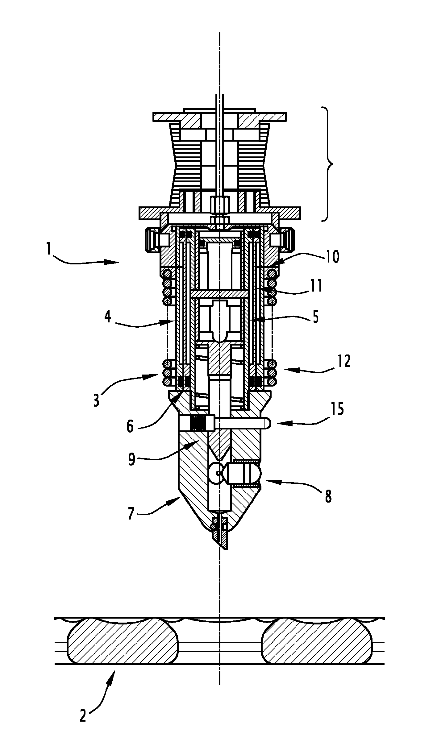
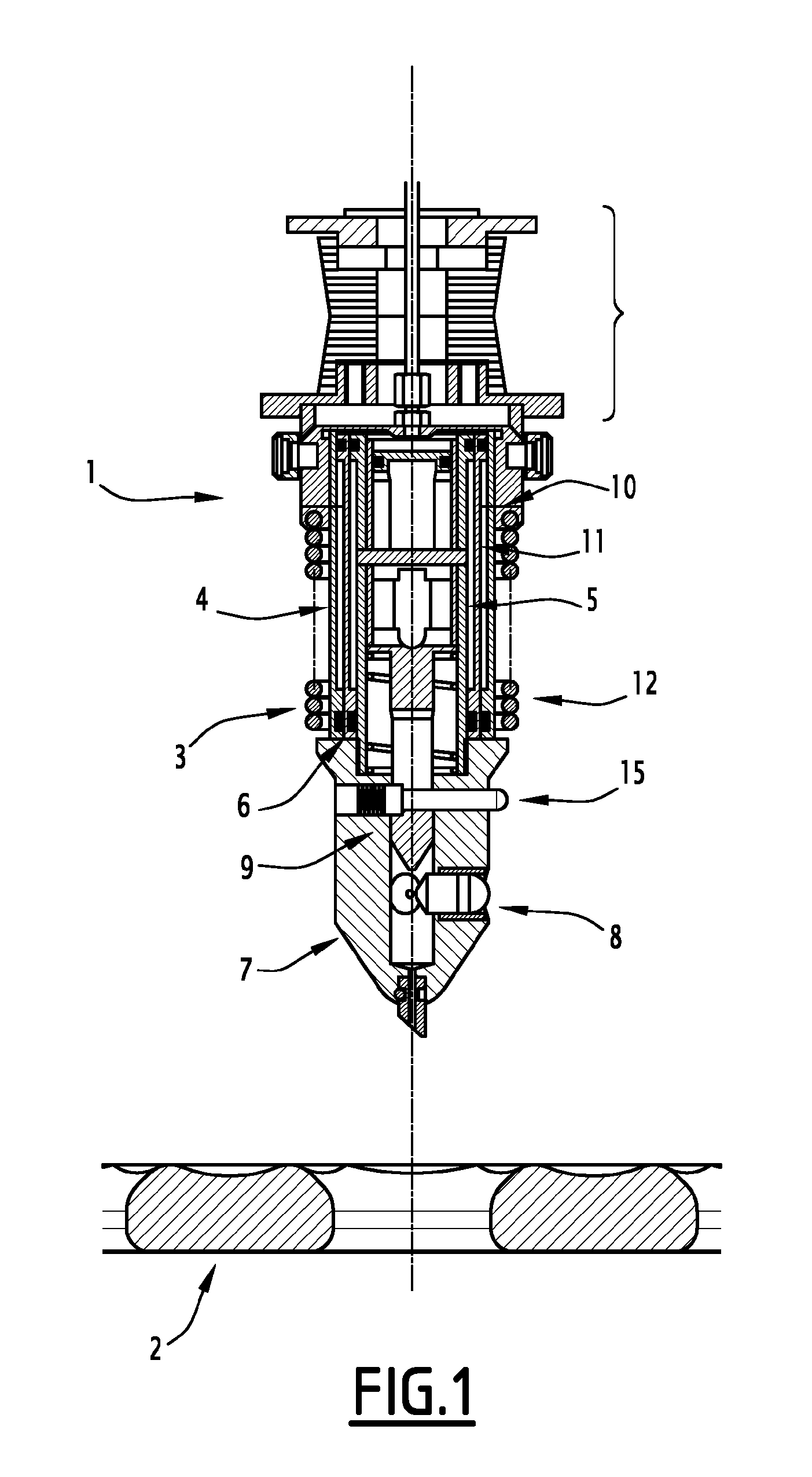
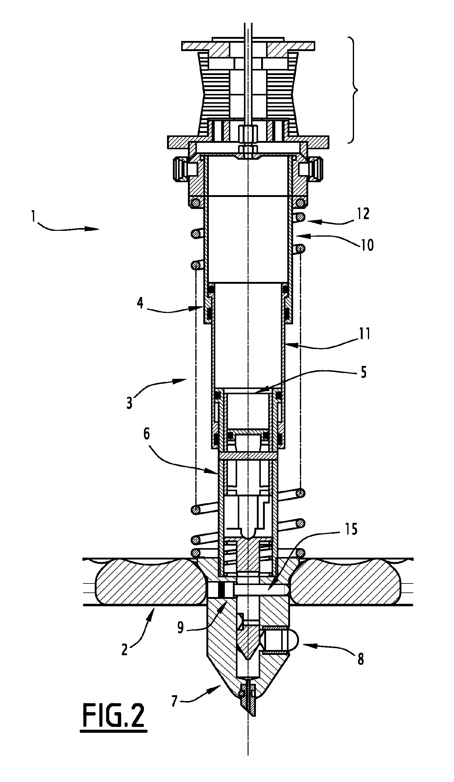
[0030]These figures, and in particular FIGS. 1 and 2, illustrate an anchoring harpoon, intended in particular for an aircraft on a platform of the military vessel type or another type.

[0031]The aircraft can for example be a rotary-wing drone.

[0032]This harpoon is designated by general reference 1 in these figures and is adapted to cooperate with an anchoring grate of the platform, this grate being designated by general reference 2 in these figures.

[0033]Indeed, the harpoon includes jack means designated by general reference 3, including cylinder means designated by general reference 4, wherein piston means designated by general reference 5 move.

[0034]These piston means are provided with a rod 6 extending beyond the cylinder means and whereof the free end includes a harpoon head that hooks in the grate, said harpoon head being designated by general reference 7.

[0035]In fact and as described in the aforementioned prior art document, this harpoon head is provided with retaining fingers...


PUM


Abstract

An anchoring harpoon intended in particular for an aircraft, capable of cooperating with an anchoring grate of a platform, includes jack elements including a cylinder element containing mobile piston elements provided with a rod that extends beyond the cylinder element, the free end of which includes a harpoon head (7) that is hooked in the grate and includes retaining fingers (8, 13, 14) that can be moved between a retracted position and an active position by control elements (9). The control element (9) for controlling the movements of the fingers include a control piston (18) which can slide inside the rod of the jack and which is associated with a bistable actuator (19) of the fingers, capable of moving between a retracted position and an active position in which the fingers are deployed with the application of successive pressure pulses in the jack elements.

Description

[0001]The present invention concerns an anchoring harpoon intended in particular for an aircraft able to cooperate with an anchoring grate of a platform, and an anchoring system including one such harpoon.[0002]Such harpoons and such anchoring systems are already generally known in the state of the art.[0003]Thus for example, document FR-A-2 701 689 describes a harpoon intended to equip a rotocraft such as a helicopter, for example, and that can be pulled towards a landing platform of a vessel so that the head of the harpoon attaches on the grate and thus forms an anchoring point of the aircraft, in particular facilitating the landing operation thereof.[0004]The anchoring harpoon described in the aforementioned document includes cylinder means wherein piston means move provided with a shaft extending beyond the cylinder means and the free end of which includes a harpoon head for hooking in the grate. This harpoon head is in fact provided with retaining fingers for retention in the g...

Claims


Application Information

Patent Timeline
Patent Type & Authority Patents(United States)
IPC IPC(8): B64F1/12
CPCB64F1/16F16B21/16B64C2201/182B64F1/125B64U70/30B64F1/12
Inventor AFFRE, DE, SAINT, ROME, RONAN
Owner DCNS SA
Why Eureka
Try Eureka