Method and system for 3D display calibration with feedback determined by a camera device

a camera device and feedback technology, applied in the field of system and method for calibrating a 3d display, can solve the problems of poor viewing experience with occupied off-axis seating, limited amount, and loss of typical digital 3d technology light transmission, and achieve the effect of facilitating efficient management of screen-specific configurations

Active Publication Date: 2014-05-27
DOLBY LAB LICENSING CORP
View PDF36 Cites 14 Cited by
  • Summary
  • Abstract
  • Description
  • Claims
  • Application Information

AI Technical Summary

Benefits of technology

[0020]HHD-based calibration methodology may be desirable in managing variations on projection screen gains. Typical digital 3D technologies lose significant amount of light transmission due to filters in light path and 3-D glasses. An exemplary theater has multiple screens, some or all of which may or may not have identical gains, dimensional or geometrical shapes. Since projectors are not necessarily stationary and could be wheeled to different screening rooms in a multiplex, data collected on varied gains will facilitate efficient management of screen-specific configurations. The result may be an efficient mechanism in managing multiple screens of varied amount of reflected light levels, regardless of screen classification, geometrical shapes or projection technologies.
[0021]In another embodiment, the HHD-based calibration system may be employed in a circular polarization system and may act as a dynamic seat map generator, identifying seats that are subjected to ghosting or hot-spotting. In this way, affected seats could be blocked out to ensure a premium viewing experience for the patron. With circular polarization, a silver screen is necessary in order to maintain circular polarization and increased level of brightness. The use of the silver screen creates hot spots while reducing the number of seats in the sweet spot. This is due to the limited amount of light generated from the projector in off axis seating which includes many seats to the leftmost and rightmost of the screen. When 2D content is played back in the same auditorium, the presence of the hot spot results in a poor viewing experience with occupied off axis seating.

Problems solved by technology

Typical digital 3D technologies lose significant amount of light transmission due to filters in light path and 3-D glasses.
This is due to the limited amount of light generated from the projector in off axis seating which includes many seats to the leftmost and rightmost of the screen.
When 2D content is played back in the same auditorium, the presence of the hot spot results in a poor viewing experience with occupied off axis seating.

Method used


Image

  • Method and system for 3D display calibration with feedback determined by a camera device
  • Method and system for 3D display calibration with feedback determined by a camera device
  • Method and system for 3D display calibration with feedback determined by a camera device

Examples


Embodiment Construction

[0040]Embodiments of the inventive system and method will be described with reference to FIGS. 1-3.

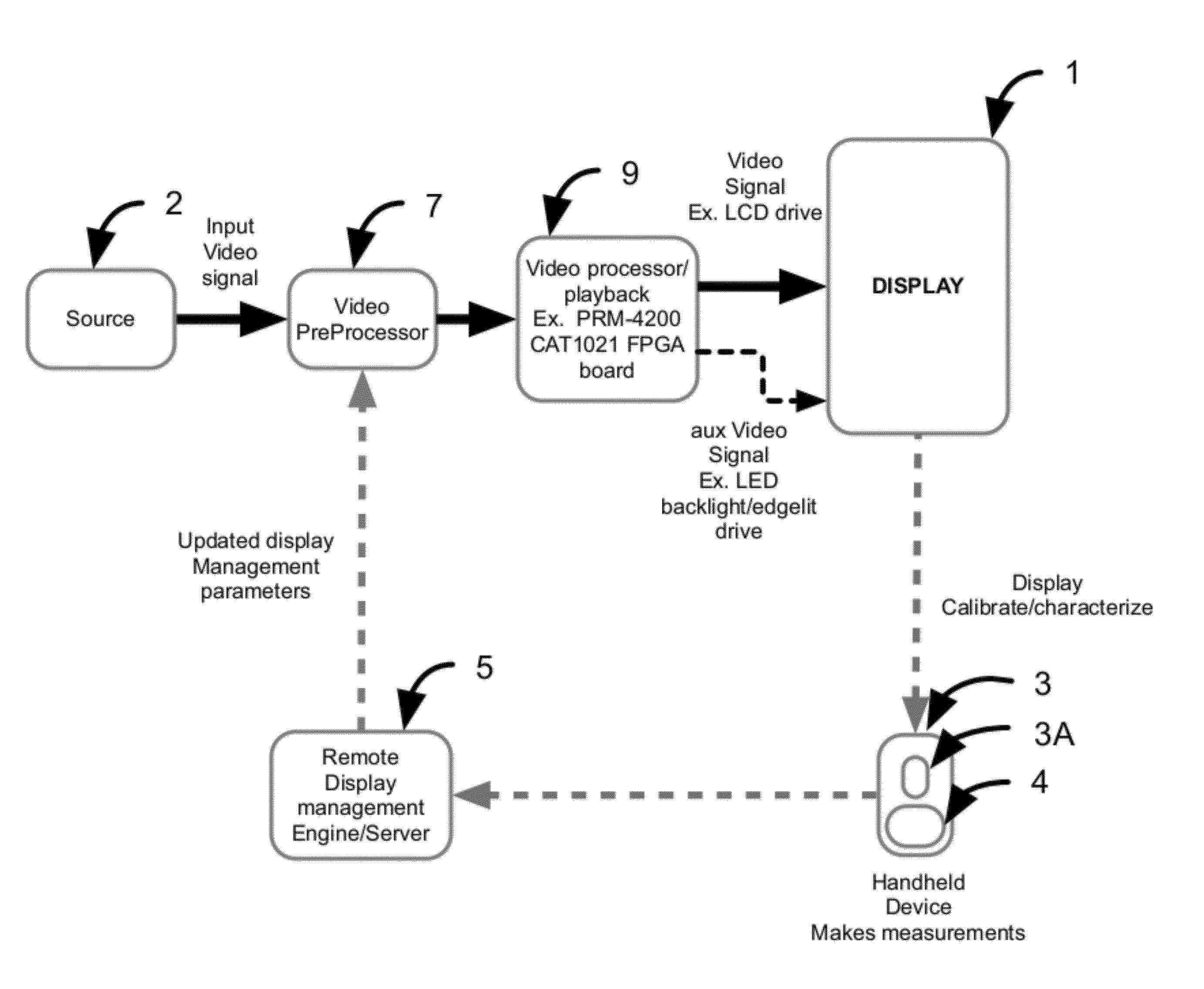
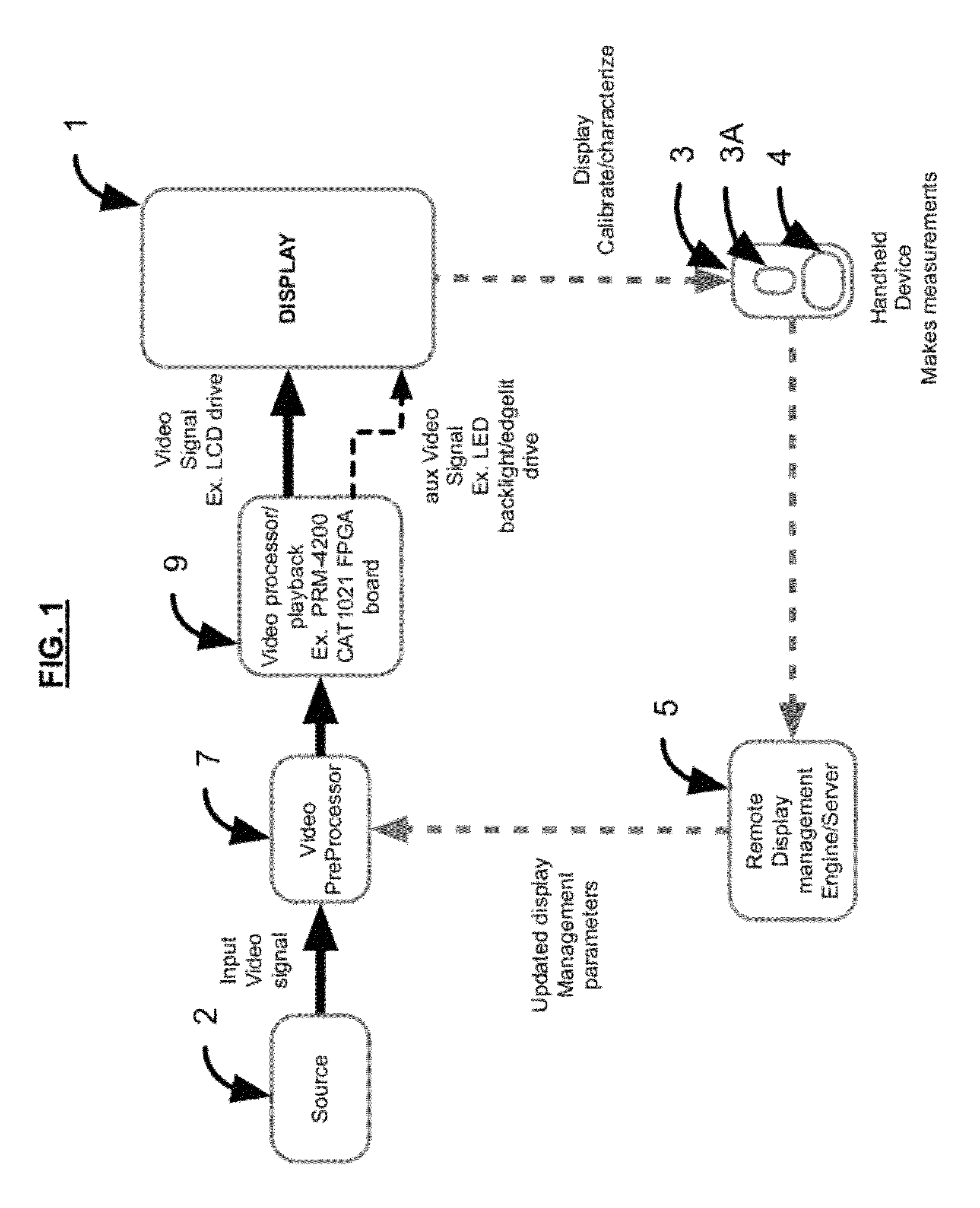
[0041]FIG. 1 is a block diagram of an embodiment of the inventive system. The system of FIG. 1 includes display device 1 configured to display images sequentially in response to a video input signal from source 2. Display device 1 may be implemented as any of a variety of display devices, (e.g., a standard LCD display, a high contrast LCD display, or another display device). For example, in a class of implementations, device 1 is an LED or LCD display including a front panel (comprising an array of LCD or LED pixels) and a backlighting (or edge-lighting) system for illuminating the pixels of the front panel. A backlighting system typically includes a backlight panel comprising an array of individually controllable LEDs. An edge-lighting system typically includes individually controllable LEDs arranged along edges of a front panel, and a subsystem which directs light from these LEDS to ...


PUM


Abstract

Several embodiments of 3D display system and systems and methods for their calibration are disclosed herein. In one embodiment, a method and system for calibrating a 3D display using feedback indicative of measurements of light, emitted from the 3D display (typically during display of a test pattern), by a camera device. In one embodiment, the camera device is a handheld camera device including an inexpensive, uncalibrated camera. In another class of embodiments, a system including a 3D display (to be recalibrated), a video preprocessor coupled to the display, and a feedback subsystem including a camera device operable to measure light emitted by the display are also disclosed.

Description

CROSS-REFERENCE TO RELATED APPLICATIONS[0001]This Patent Application is a Continuation-in-Part (CIP) Application, and claims the benefit of, a co-pending Application with a Ser. No. 12 / 888,873 filed by a common Inventor of this Application on Sep. 23, 2010. The disclosure made in the application Ser. No. 12 / 888,873 is hereby incorporated by reference in its entirety.BACKGROUND OF THE INVENTION[0002]1. Field of the Invention[0003]Some embodiments of the invention relate to systems and methods for calibrating a 3D display and, more particularly, to using a camera device (e.g., a handheld camera device) to calibrate such 3D displays.[0004]2. Background of the Invention[0005]Throughout this disclosure including in the claims, the expression performing an operation “on” signals or data (e.g., filtering or scaling the signals or data) is used in a broad sense to denote performing the operation directly on the signals or data, or on processed versions of the signals or data (e.g., on versi...

Claims


Application Information

Patent Timeline
Patent Type & Authority Patents(United States)
IPC IPC(8): H05B41/36H04N13/04H04N17/02
CPCH04N13/0425H04N13/0257H04N13/02H04N13/20H04N13/257H04N13/327
Inventor HOVANKY, THAOERINJIPPURATH, GOPAL
Owner DOLBY LAB LICENSING CORP
Why Eureka
Try Eureka