
Small form factor variable optical attenuator with cladding mode suppressing fiber

a technology of optical attenuators and fibers, applied in the field of variable optical attenuators, can solve the problems of increasing the need for channel power equalization, increasing the cost and complexity of optical networks, and increasing wdl and pdl

Active Publication Date: 2014-05-27
LUMENTUM OPERATIONS LLC
View PDF14 Cites 1 Cited by
  • Summary
  • Abstract
  • Description
  • Claims
  • Application Information

AI Technical Summary

Benefits of technology

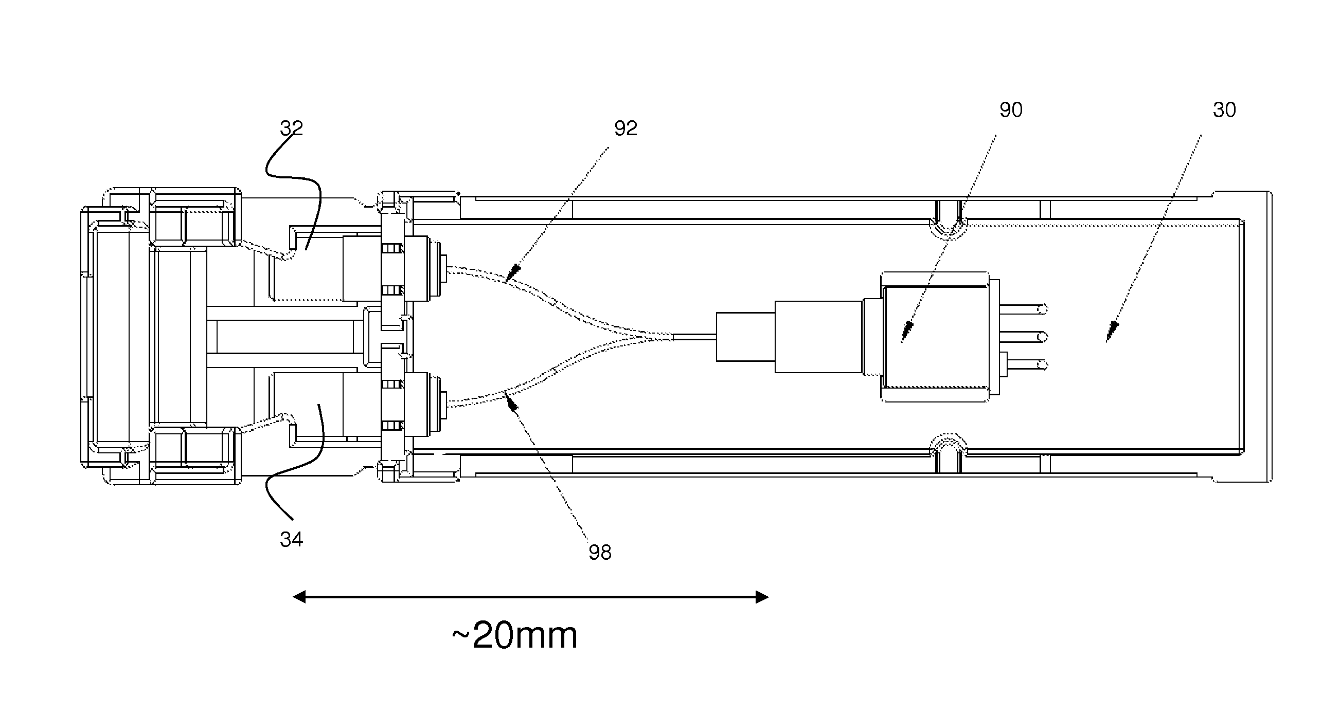
The invention uses a special fiber to suppress certain modes of light in order to improve the quality of optical signals in a certain type of connector. By doing this, the fiber can achieve better performance without needing to be very long.

Problems solved by technology

WDL and PDL are undesirable because they contribute to increasing differences in optical power between wavelength channels, which in turn increases the need for channel power equalization and increases the cost and complexity of optical networks.
However, compared to the stand-alone pigtailed ES-VOA, the SFP VOA suffers from higher WDL and higher PDL.
This large amount of light propagating in the cladding mode can couple back into the core of the single mode output fiber and interfere with light that propagated in the fiber lowest order mode resulting in modal noise.
This offers no teaching for mitigating the PDL degradation experienced by the SFP VOA.
At high attenuation, given that most of the optical power is in the cladding modes, this effect leads to significant PDL degradation.
This difference in coupling would also contribute to PDL degradation.

Method used


Image

  • Small form factor variable optical attenuator with cladding mode suppressing fiber
  • Small form factor variable optical attenuator with cladding mode suppressing fiber
  • Small form factor variable optical attenuator with cladding mode suppressing fiber

Examples


Embodiment Construction

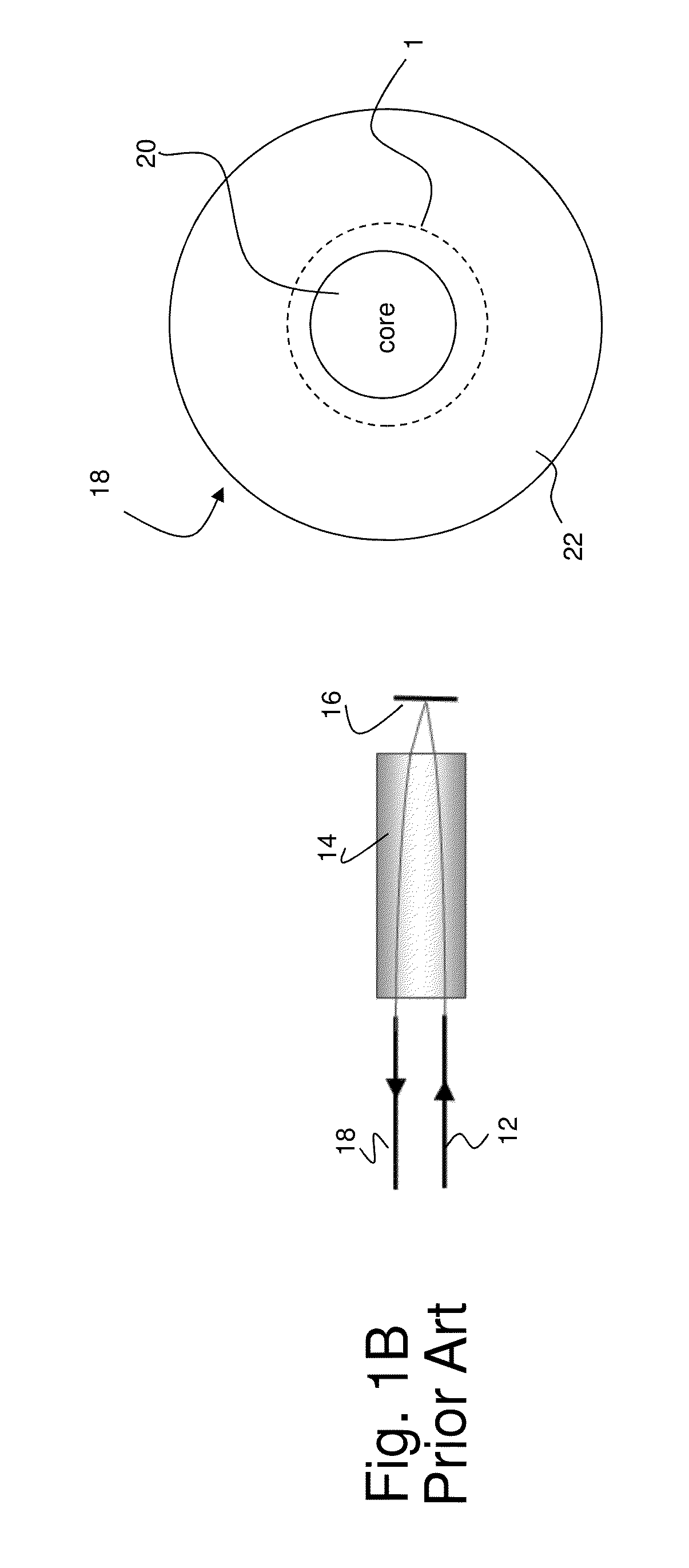
[0034]A prior art VOA technology based on a Electro-Static (ES) Micro-Electro-Mechanical (MEMS) chip, is illustrated in FIG. 1A. The ES-VOA component 10 has an input optical fiber 12, a lens 14, a MEMS tilting minor 16 and an output optical fiber 18. The lens 14 focuses the input light onto the MEMS tilting minor 16, the reflected light is directed towards the output fiber 18. Input optical fiber 12 and output optical fiber 18 are supported in ferrule 13. A voltage is applied to the MEMS chip, and the voltage amplitude controls the mirror tilt angle. By varying the voltage and minor tilt angle, the position of the reflected spot on the output fiber is varied. With the output spot aligned to the center of output fiber core, shown in FIG. 1B, the attenuation is minimum and limited only by the insertion loss (typically ˜0.5 dB). As the output spot 1, of the beam of reflected light, is misaligned relative to the output fiber core 20, as seen in FIG. 1C, the amount of light launched into...


PUM


Abstract

The invention relates to an electro-static variable optical attenuator suitable for use in a small form factor pluggable module. A short cladding suppressing fiber, such as a double clad optical fiber, dissipates attenuated light coupled to the cladding to reduce modal interference in the output light, while also reducing PDL and WDL introduced by the off set attenuation mechanism.

Description

FIELD OF THE INVENTION[0001]This invention relates generally to a variable optical attenuator integrated into a small form factor module including a short double clad fiber to suppress cladding modes and reduce polarization dependent loss (PDL) and wavelength dependent loss (WDL).BACKGROUND OF THE INVENTION[0002]Variable Optical Attenuators (VOAs) are common components used in optical communication networks. One common VOA technology is based on an Electro-Static (ES) Micro-Electro-Mechanical (MEMS) chip. The ES-VOA component has an input optical fiber, a lens, a MEMS tilting minor and an output optical fiber. The lens focuses the input light onto the MEMS tilting mirror, and the reflected light is directed towards the output fiber. A voltage is applied to the MEMS chip, the voltage amplitude controls the mirror tilt angle. By varying the voltage and minor tilt angle, the position of the reflected spot on the output fiber is varied. With the output spot aligned to the center of outp...

Claims


Application Information

Patent Timeline
Patent Type & Authority Patents(United States)
IPC IPC(8): G02B6/32
CPCG02B6/266G02B26/02G02B6/4256
Inventor WANG, ZHONGJIANAYLIFFE, MICHAELYU, QINRONGLIU, NIKIFAN, RONGTANG
Owner LUMENTUM OPERATIONS LLC
Learn More