Mixer with carrier leakage calibration

a technology of carrier leakage and mixer, applied in the direction of instruments, electric/magnetic computing, computation using denominational number representation, etc., can solve the problem of high flicker noise level

Active Publication Date: 2009-04-21
MEDIATEK SINGAPORE PTE LTD SINGAPORE
View PDF3 Cites 7 Cited by
  • Summary
  • Abstract
  • Description
  • Claims
  • Application Information

AI Technical Summary

Benefits of technology

[0009]Embodiments according to the invention provide a mixer circuit with carrier-leakage calibration. In the embodiments, local oscillator (LO) signal coupling to a differential output signal of the mixer circuit is significantly suppressed. In addition, this carrier-leakage calibration has negligible degradation in the matching between an I-Quad mixer and a Q-Quad mixer in a quadrature mixer circuit.

Problems solved by technology

Mixer circuits for high frequency application constructed using metal oxide semiconductor (MOS) transistors are subject to a limited voltage supply (usually less than 2V) and high levels of flicker noise, having frequencies extending up to several tens of MHz.

Method used


Image

  • Mixer with carrier leakage calibration
  • Mixer with carrier leakage calibration
  • Mixer with carrier leakage calibration

Examples


Embodiment Construction

[0017]The following description is of the best-contemplated mode of carrying out the invention. This description is made for the purpose of illustrating the general principles of the invention and should not be taken in a limiting sense. The scope of the invention is best determined by reference to the appended claims.

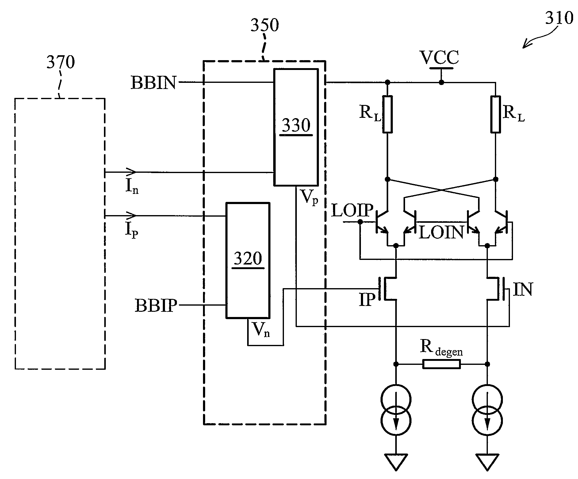
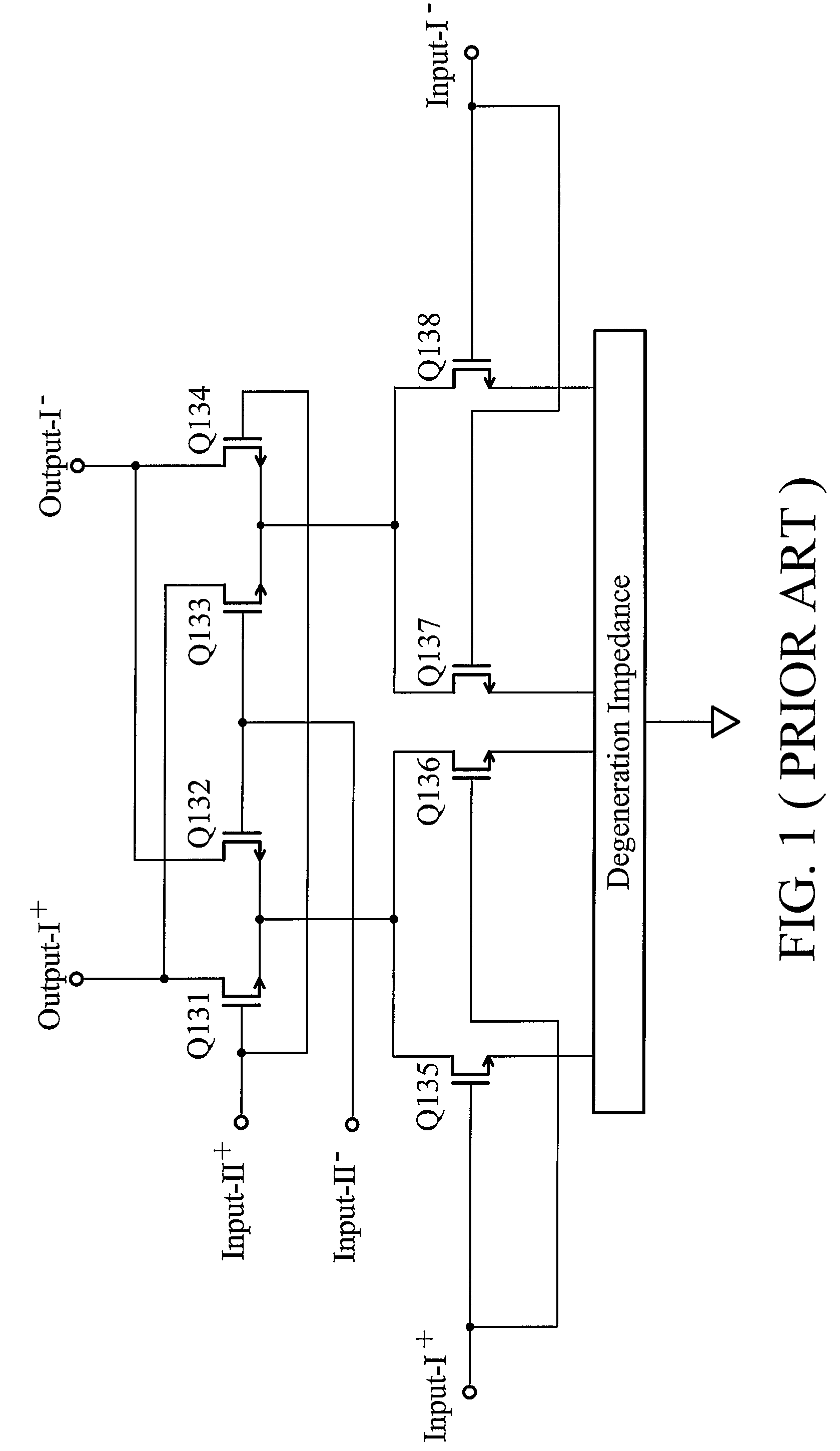
[0018]FIG. 3 is a block diagram of a mixer circuit according to an embodiment of the invention. The mixer circuit 300 comprises a double-balanced mixer 310 and a carrier-leakage calibration cell 350. The double-balanced mixer has input pairs LOIP / LOIN and an input pair IP / IN. The double-balanced mixer in FIG. 3 differs only from that in FIG. 1 in that differential pairs of MOSFETs are replaced by bipolar junction transistors (BJTs). The input pairs LOIP / LOIN receives a differential local oscillator signal and provides a differential output signal through load resistor RL. The carrier-leakage calibration cell 350 receives a differential baseband (BB) signal and a differ...


PUM


Abstract

A mixer circuit. The mixer circuit comprises a double-balanced mixer and a carrier-leakage calibration cell. The double-balanced mixer has first and second input pairs whereby the first input pair receives the first differential input signal. The carrier-leakage calibration cell receives the second differential input signal and a differential calibration current and generates first and second output voltages to the second input pair of the double-balanced mixer.

Description

BACKGROUND OF THE INVENTION[0001]1. Field of the Invention[0002]The invention relates to a double-balanced mixer and, in particular, to a double-balanced mixer with a dynamic current steering cell.[0003]2. Description of the Related Art[0004]Mixer circuits for high frequency application constructed using metal oxide semiconductor (MOS) transistors are subject to a limited voltage supply (usually less than 2V) and high levels of flicker noise, having frequencies extending up to several tens of MHz. Accordingly, the gain and output signal levels required in such mixer circuits exceed those allowed in the equivalent bipolar circuits.[0005]FIG. 1 is a circuit diagram illustrating a conventional double-balanced mixer circuit. The double-balanced mixer circuit in FIG. 1 includes differential pairs of MOSFETs (Q131-Q132 and Q133-Q134). The drains of the pairs of MOSFETs are connected to an output terminal (Output-I+ and Output-I−). The gates of the pairs of MOSFETs are connected to first i...

Claims


Application Information

Patent Timeline
Patent Type & Authority Patents(United States)
IPC IPC(8): G06G7/12
CPCH03D7/145H03D7/1458H03D7/165H03D2200/009
Inventor NG, CHOON YONGKHOO, EE SZE
Owner MEDIATEK SINGAPORE PTE LTD SINGAPORE
Why Eureka
Try Eureka