
Method and apparatus for fractional RF signal synthesis

a fractional rf signal and signal synthesis technology, applied in pulse automatic control, analogue computers, analog and hybrid computing, etc., can solve the problems of low phase noise, low phase noise, and limited frequency agility, and achieve the effect of prolonging the delay

Active Publication Date: 2006-08-01
VECIMA NETWORKS
View PDF6 Cites 6 Cited by
  • Summary
  • Abstract
  • Description
  • Claims
  • Application Information

AI Technical Summary

Benefits of technology

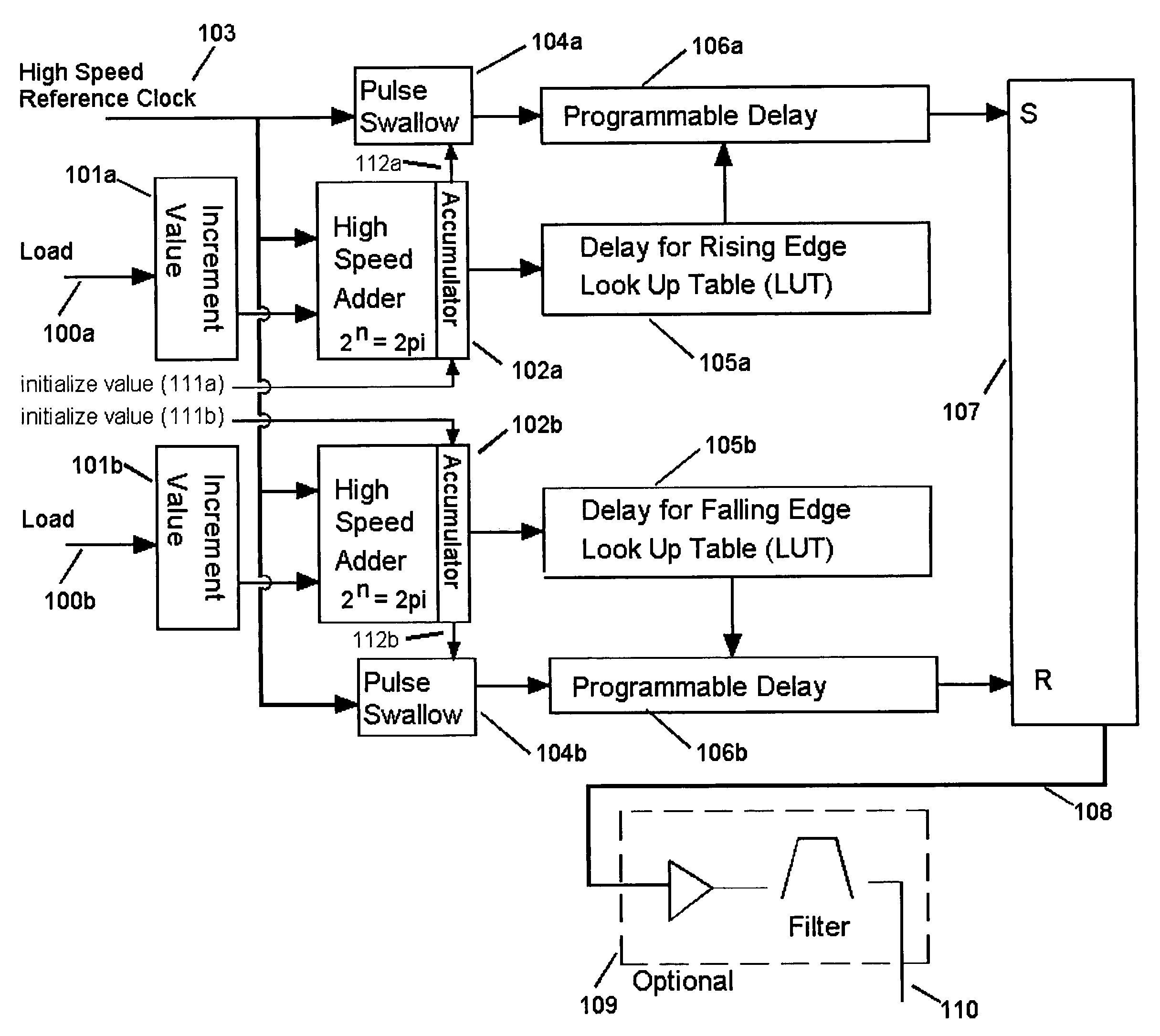
"The present invention provides an apparatus for generating an RF signal with superior phase noise and frequency resolution. The apparatus includes a high speed reference clock, programmable digital delay elements, and a signal combining element. The output frequency is determined by an increment value and the duty cycle is controlled by the difference in the start values of two accumulators. The phase delay is calibrated using a look up table or microprocessor. The apparatus can produce the RF signal from a wide frequency range and is suitable for digital ASIC implementation with no external components. The invention also provides a method for generating any desired lower frequency from DC to the reference input frequency."

Problems solved by technology

In communication systems, the basic RF oscillator is used in conjunction with additional circuitry to stabilize the frequency of the oscillator as typical free running RF oscillators are not stable enough for most communication systems.
This method yields a high phase noise performance but suffers from very limited frequency agility.
However a PLL with lower loop bandwidth thus has to be used which consequently degrades the phase noise.
This method suffers from limitations to the PLL implementation.
It also faces additional problems with frequency agility as well as the jitter introduced by the delay lock loop because of mismatched delays.
This method results in very fine frequency resolution, but produces undesired spurious signals and the output signal frequency is limited by the speed of the DAC.
This method is limited in its factional capability and still uses a VCO, phase detector, and loop filter.
Normal conflict between better phase noise and higher frequency resolution still exists for this method.

Method used


Image

  • Method and apparatus for fractional RF signal synthesis
  • Method and apparatus for fractional RF signal synthesis
  • Method and apparatus for fractional RF signal synthesis

Examples


Embodiment Construction

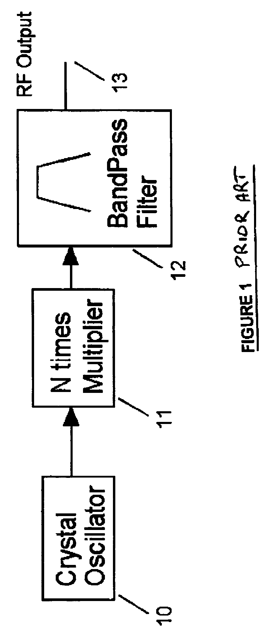
[0049]FIG. 1 illustrates the first method mentioned above where a crystal oscillator 10 is subjected to a nonlinearity in order to realize a frequency multiplier 11. The desired multiplied frequency is filtered using a band pass filter 12, resulting in the RF output frequency 13. This method yields a high phase noise performance but suffers from very limited frequency agility.

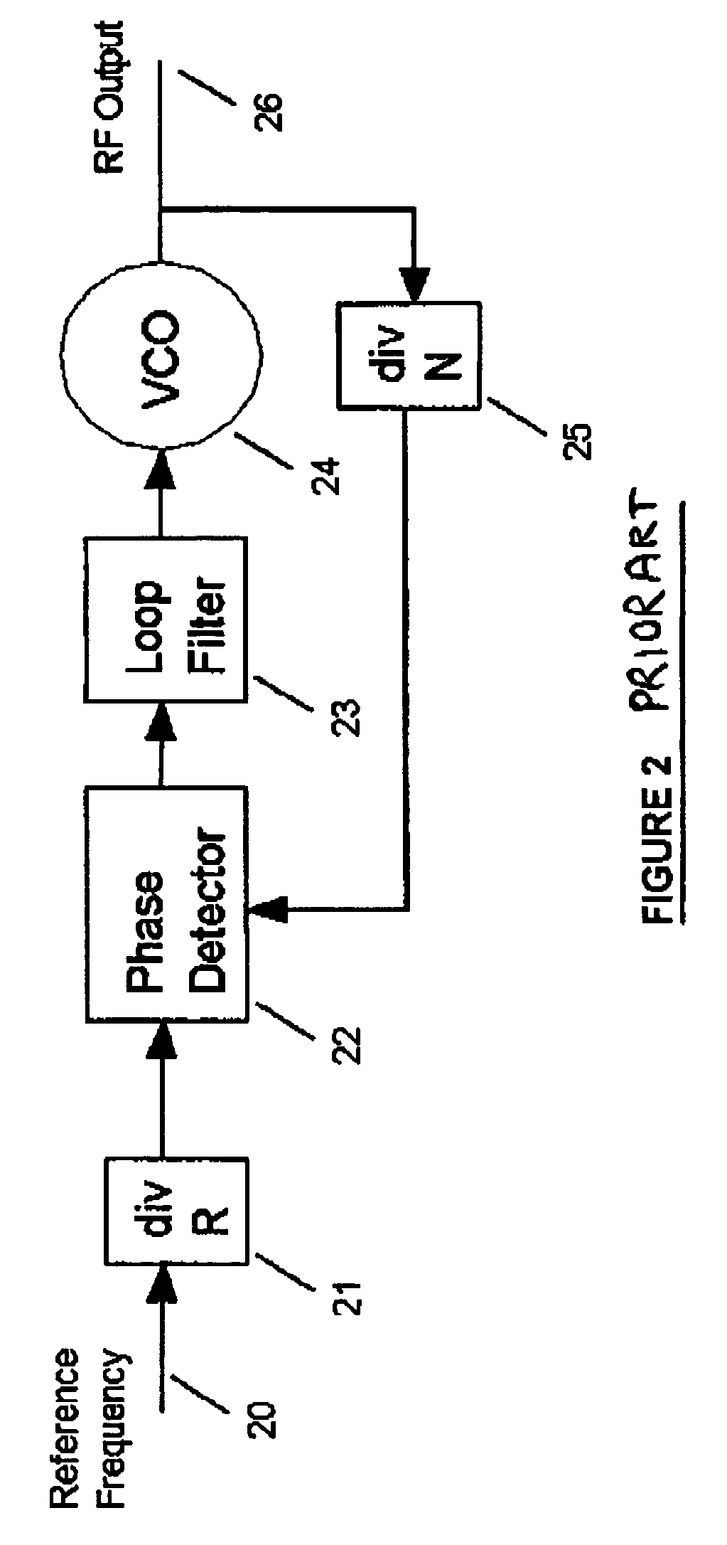
[0050]The basic principal of a PLL as mentioned in the second method above is shown in FIG. 2. As illustrated in the figure, a stable reference frequency 20 is divided down 21. The output RF signal frequency 26 is also divided down 25. The two divided frequency signals are then fed to the phase detector 22 for phase comparison. The phase detector 22 is used to produce an error signal that is filtered 23 with the required loop bandwidth to lock the RF oscillator 24 frequency to the reference frequency 20. The phase noise performance of the free running oscillator is worse than the reference crystal oscillator in...


PUM


Abstract

The present invention provides a method to improve the frequency resolution and phase noise of a synthesized RF signal. It also results in the superior characteristics of instantaneous frequency changeability, wide frequency setting ability, and fully digital ASIC implementation ability. The synthesized RF signal is generated from a higher reference frequency using a variable pulse stretching technique. The amount of the pulse stretch in each cycle is controlled by a phase increment value and is implemented using programmable delay lines. Pulse stretching is extended beyond one cycle by pulse swallowing, allowing the generation of an RF signal from DC up to the input reference clock signal frequency.

Description

[0001]This application claims priority under 35 U.S.C. 119 from Provisional Application Ser. No. 60 / 511,677 filed Oct. 17, 2003.[0002]This invention relates generally to telecommunication systems. The present invention relates more specifically to a method of synthesizing an RF signal used in telecommunication systems.[0003]This application is related to applications filed on the same day by the same inventors under application Ser. No. 10 / 796,416 entitled APPARATUS FOR DIGITAL VECTOR QAM MODULATOR and application Ser. No. 10 / 796,415 entitled APPARATUS FOR FRACTIONAL RF SIGNAL SYNTHESIS WITH PHASE MODULATION the disclosures of which are incorporated herein by reference.BACKGROUND OF THE INVENTION[0004]In communication systems an oscillator is used as a fundamental building block. Oscillators are commonly used for up and down frequency conversion. They are also required for subsystems such as a direct modulator. The quality of a fixed frequency oscillator is measured by the frequency...

Claims


Application Information

Patent Timeline
Patent Type & Authority Patents(United States)
IPC IPC(8): H03B19/00H03B21/02H03K5/13H03K5/156H03L7/00
CPCH03B21/02H03K5/1565H03K5/133
Inventor HARRON, GERALDKUMAR, SURINDER
Owner VECIMA NETWORKS
Learn More