Unmanned aircraft system and operation method thereof

a technology of unmanned aircraft and flight path, which is applied in the direction of launching/towing gear, process and machine control, instruments, etc., can solve the problems of unattractive cargo shipment approaches of conventional unmanned aircraft for landing and taking off, and the lack of communication links between ground controllers and unmanned aircra

Active Publication Date: 2014-06-03
MITSUBISHI HEAVY IND LTD
View PDF17 Cites 69 Cited by
  • Summary
  • Abstract
  • Description
  • Claims
  • Application Information

AI Technical Summary

Problems solved by technology

According to Specification of U.S. Pat. No. 6,540,179, landing and take-off of an unmanned aircraft presents problems in providing necessary communication links between ground controllers and the unmanned aircraft.
Operation of unmanned aircraft from typical airports presents a potential safety problem to other aircraft and populated areas, thereby making conventional unmanned aircraft approaches for cargo shipment unattractive.

Method used


Image

  • Unmanned aircraft system and operation method thereof
  • Unmanned aircraft system and operation method thereof
  • Unmanned aircraft system and operation method thereof

Examples


first embodiment

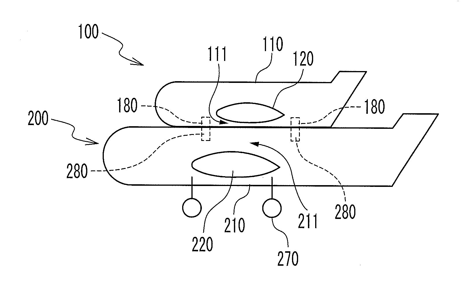
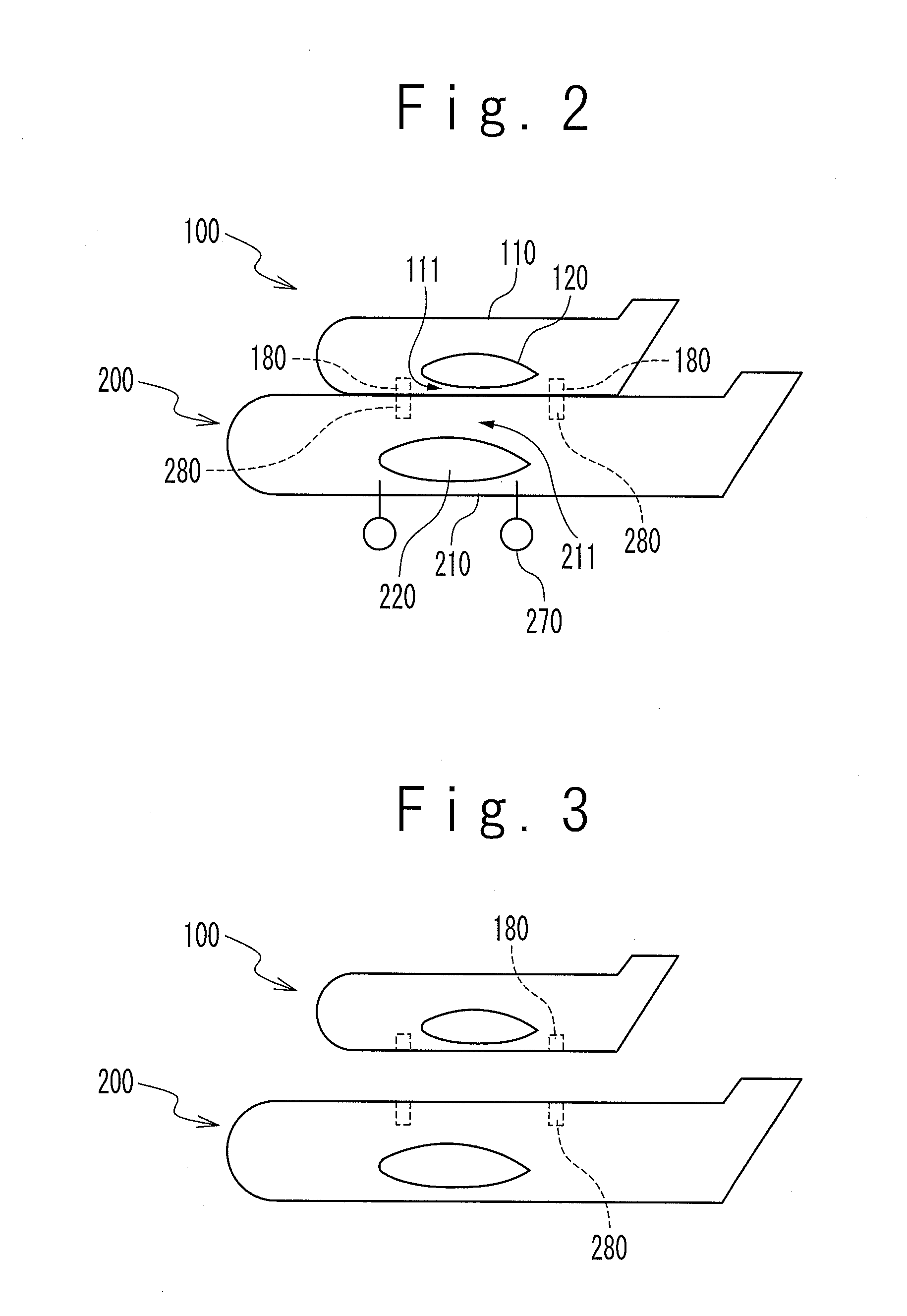
[0042]As shown in FIG. 2, an unmanned aircraft system according to a first embodiment of the present invention includes a manned aircraft 100 and an unmanned aircraft 200. The manned aircraft 100 includes a fuselage 110, a main wing 120, joining mechanisms 180 provided at a bottom portion 111 of the fuselage 110, and a landing system. In FIG. 2, the landing system of the manned aircraft 100 is housed in the fuselage 110 or the main wing 120. The joining mechanisms 180 include a joining mechanism 180 on a nose side and a joining mechanism 180 on a tail side. The unmanned aircraft 200 includes a fuselage 210, a main wing 220, joining mechanisms 280 provided at a roof portion 211 of the fuselage 210, and a landing system 270. The joining mechanisms 280 include a joining mechanism 280 on a nose side and a joining mechanism 280 on a tail side. When the joining mechanisms 180 and the joining mechanisms 280 are joined to each other, the manned aircraft 100 and the unmanned aircraft 200 for...

second embodiment

[0069]Referring to FIG. 8, an unmanned aircraft system according to a second embodiment of the present invention will be described. The unmanned aircraft system according to the present embodiment is the same as the unmanned aircraft system according to the first embodiment except that the unmanned aircraft joined-case flight state signal is inputted not into the flight control computer 240 but into the flight control computer 140.

[0070]A flight control in a case that the manned aircraft 100 and the unmanned aircraft 200 are joined will be described. The piloting interface 131 generates a joined-case pilot command signal in response to an operation by the pilot 101. The flight sensor 134 generates a manned aircraft joined-case flight state signal indicating a flight state of the manned aircraft 100. The flight sensor 234 generates an unmanned aircraft joined-case flight state signal indicating a flight state of the unmanned aircraft 200. The flight control computer 140 generates a m...


PUM


Abstract

An unmanned aircraft system includes a manned aircraft and an unmanned aircraft. The manned aircraft includes a manned aircraft main wing, a manned aircraft fuselage, a manned aircraft landing system, and a manned aircraft joining mechanism provided at a bottom portion of the manned aircraft fuselage. The unmanned aircraft includes an unmanned aircraft main wing, an unmanned aircraft fuselage, an unmanned aircraft landing system, and an unmanned aircraft joining mechanism provided at a roof portion of the unmanned aircraft fuselage. The manned aircraft joining mechanism and the unmanned aircraft joining mechanism are detachably joined. The unmanned aircraft system can take off or land in a state that the unmanned aircraft and the manned aircraft are joined.

Description

TECHNICAL FIELD[0001]The present invention relates to an unmanned aircraft system for joining or separating an unmanned aircraft and a manned aircraft in the air, an unmanned aircraft used in the unmanned aircraft system, a manned aircraft used in the unmanned aircraft system, and an operation method of the unmanned aircraft system.BACKGROUND ART[0002]Specification of Japanese Patent No. 2785778 discloses an air-to-air missile launching method using a carrier aircraft and a small unmanned platform aircraft. The small unmanned platform aircraft with a missile is separated from the carrier aircraft in the air. The small unmanned platform aircraft automatically turns along a predetermined flight course by using GPS (Global Positioning System) navigation. The small unmanned platform aircraft turns in the air to search and lock on a hostile aircraft. The small unmanned platform aircraft launches the missile to the locked-on hostile aircraft.[0003]According to Specification of U.S. Pat. N...

Claims


Application Information

Patent Timeline
Patent Type & Authority Patents(United States)
IPC IPC(8): B64C37/02
CPCB64C39/024B64C37/02B64C2201/206B64C2201/082G05D1/104B64U70/20B64U80/82
Inventor SUZUKI, SATOSHI
Owner MITSUBISHI HEAVY IND LTD
Why Eureka
Try Eureka