
Iron-type golf club head

a golf club head and iron-type technology, applied in the field of iron-type golf club heads, can solve the problems of/her being able to easily make a slice shot, and achieve the effects of reducing the center of gravity, and reducing the impact angl

Active Publication Date: 2014-06-03
SUMITOMO RUBBER IND LTD
View PDF15 Cites 43 Cited by
  • Summary
  • Abstract
  • Description
  • Claims
  • Application Information

AI Technical Summary

Benefits of technology

This design improves the club's ability to maintain face orientation during a swing, reduces the likelihood of slice shots, and enhances the overall directional stability of the hit golf ball by controlling the moment of inertia around the shaft axis while maintaining a low center of gravity.

Problems solved by technology

Such a golf club head a having the great moment of inertia Ic originally had a problem that when a golfer swung it, the face did not fully return to the position at address, thus causing him / her to easily make a slice shot.

Method used


Image

  • Iron-type golf club head
  • Iron-type golf club head
  • Iron-type golf club head

Examples


example

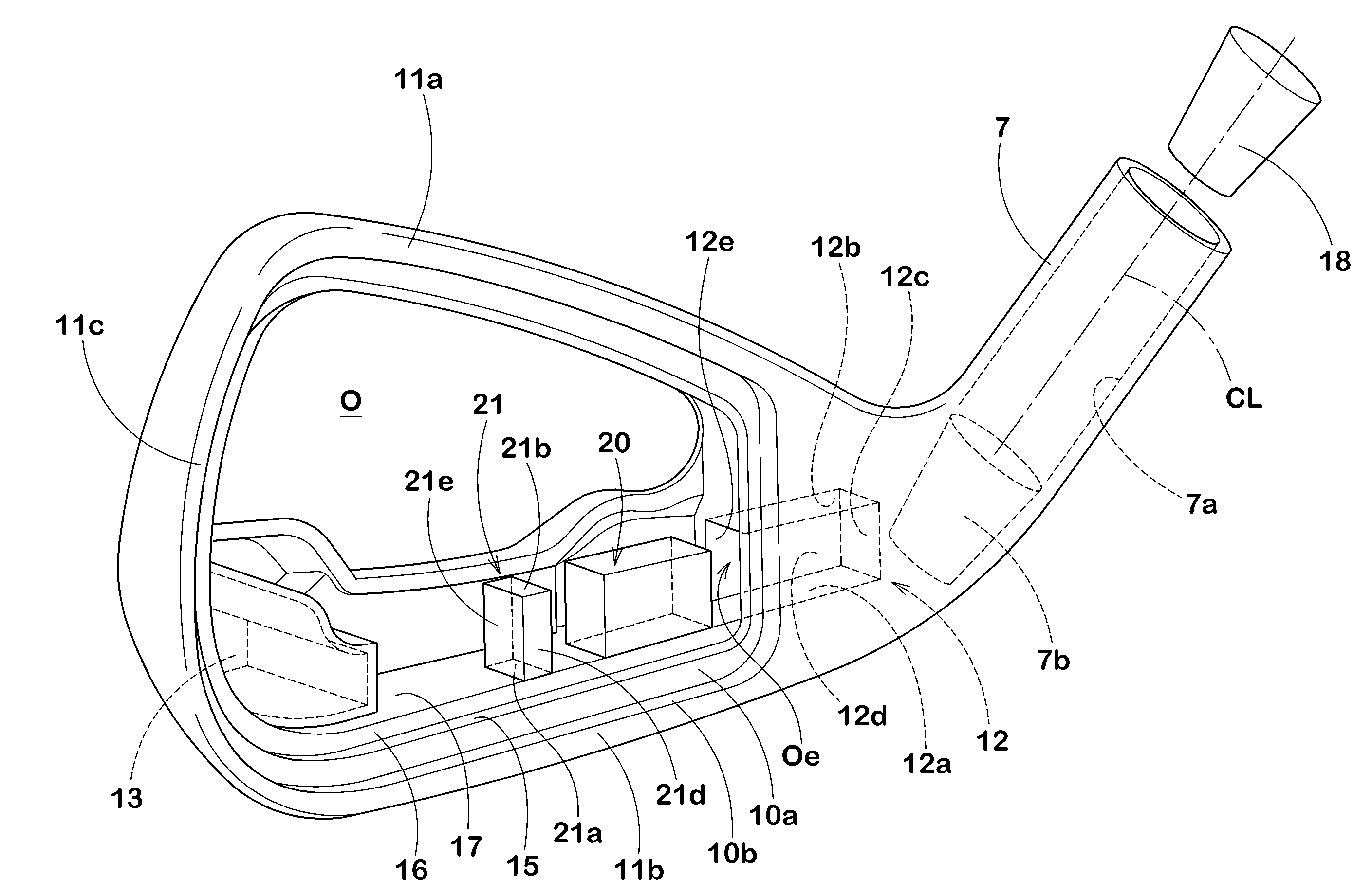
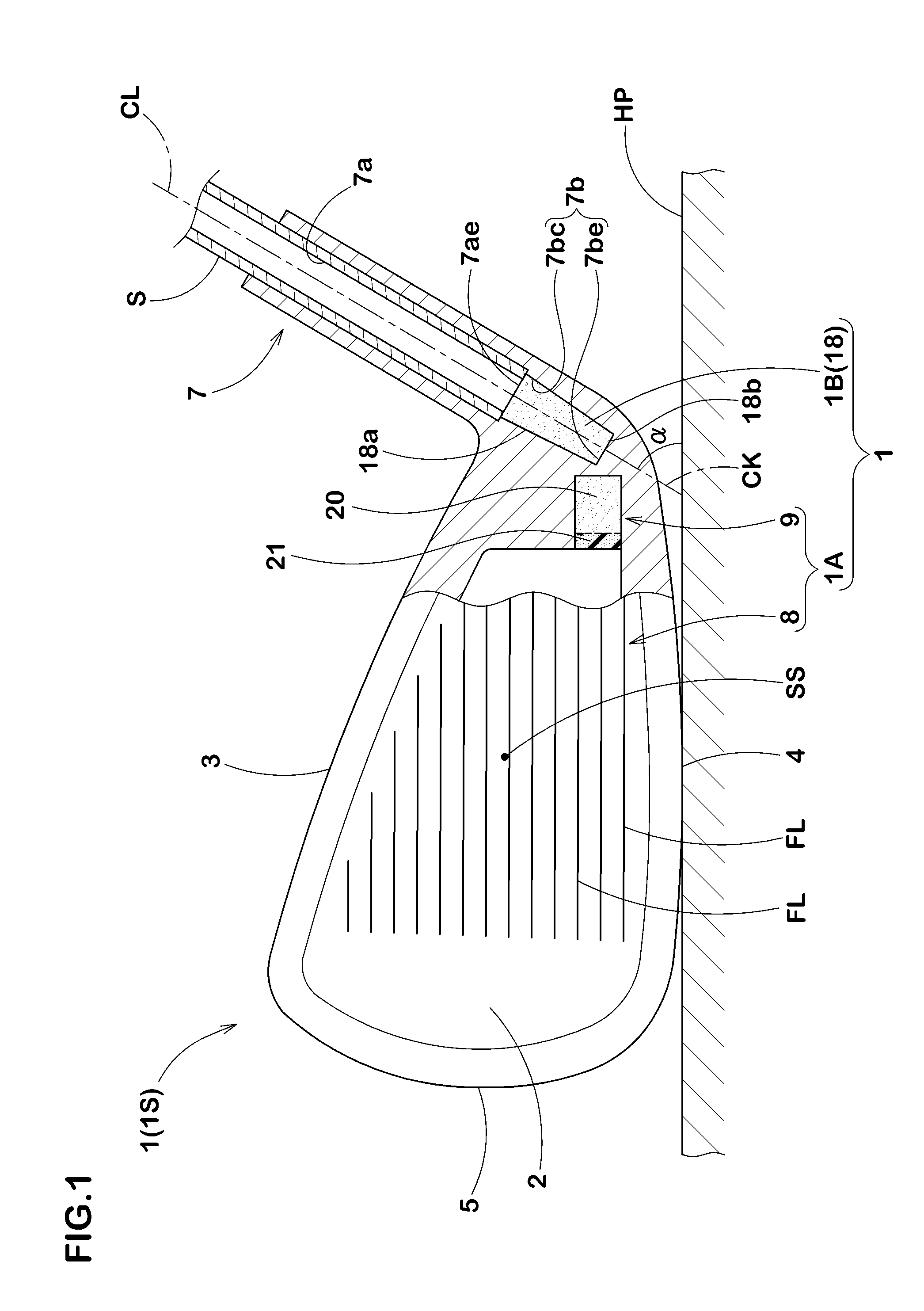
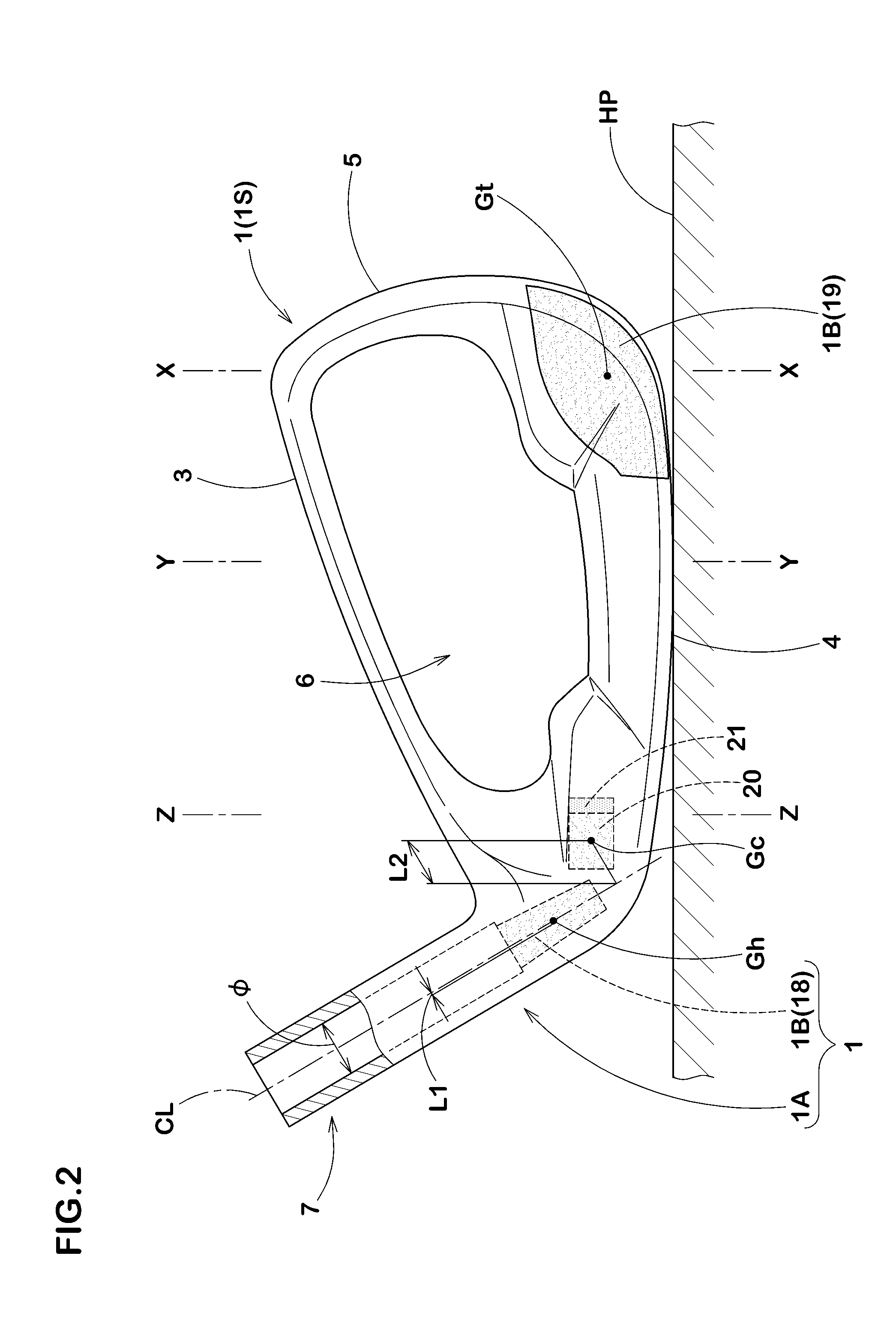
[0088]In order to ensure the effect of the present invention, iron-type golf club heads having a basic configuration as shown in FIG. 1 to FIG. 4 and based on the specification in Table 1 were prototyped and various kinds of actual hitting tests were conducted on them. Each of the heads was molded by bonding, with an adhesive and through caulking, a face receiving frame portion attached to a tubular portion formed of a casting which was made by molding SUS630 (specific gravity: 7.78) with the lost-wax precision casting method, and a face plate (specific gravity: 4.5) which is a pressed mold of Ti-6A1-4V. In addition, a head main portion was manufactured so that a center of gravity position of the head main body does not change if a position and mass of a hollow portion, a heel-side weight member, and an intermediate weight member are varied. In addition, a position to fixedly set up a bottomed hole part is provided at a same position of each head, and a position to fixedly set up a ...


PUM


Abstract

An iron-type golf club head comprises a head main portion having a face for hitting a golf ball, and weight members made of metallic material having heavier specific gravity than the head main portion. The head main portion has a tubular portion provided on a heel side of the face and having a shaft inserting hole. The tubular portion is provided continuously on the lower side of the shaft inserting hole with a bottomed hole part for arranging the weight members. The weight members include a heel-side weight member disposed in the bottomed hole part.

Description

BACKGROUND OF THE INVENTION[0001]1. Field of the Invention[0002]The present invention relates to an iron-type golf club head having improved directional stability of a hit golf ball.[0003]2. Description of the Background Art[0004]In recent years, an iron-type golf club head a position of whose center of gravity was improved by bonding more than two kinds of different metallic materials has been proposed. FIG. 10 shows one example of such an iron-type gold club head a. The club head a includes a main portion b, and weight members ct, ch having heavier specific gravity than the main portion b, the weight members ct, ch being respectively arranged in a lower part of a toe portion t and a heel portion h on a rear of a face portion of the main portion b. In this type of club head a, great mass is allocated to a toe side and a heel side of a face portion. Hence, a moment of inertia around a vertical axis passing through the center of gravity of the head G (which may be hereinafter referre...

Claims


Application Information

Patent Timeline
Patent Type & Authority Patents(United States)
IPC IPC(8): A63B53/08A63B53/04A63B53/06A63B102/32
CPCA63B2053/0433A63B2053/0491A63B59/0092A63B53/0475A63B53/047A63B2053/0416A63B2053/0408A63B60/02A63B60/54A63B53/0408A63B53/0416A63B53/0433
Inventor YAMAMOTO, AKIO
Owner SUMITOMO RUBBER IND LTD
Learn More