
Stoppers used in pre-filled syringes

a technology of stoppers and syringes, which is applied in the direction of intravenous devices, medical syringes, syringes, etc., can solve the problems of not consistently preventing reflux from occurring, affecting the maintenance of catheter lines, etc., to achieve convenient molded, high contact pressure, and high contact pressure

Active Publication Date: 2014-06-03
BECTON DICKINSON & CO
View PDF55 Cites 25 Cited by
  • Summary
  • Abstract
  • Description
  • Claims
  • Application Information

AI Technical Summary

Benefits of technology

[0008]There is a need in the art for a stopper design that creates an active seal within a syringe barrel wherein the chance for slippage of the plunger rod past the stopper taper and lodging against a front wall of the stopper is reduced. There is also a need in the art for a stopper design which is relatively short while still achieving an active seal. There is a further need in the art for a stopper design that is easily molded. There is also a need in the art for a stopper design that achieves a “positively zero” or an essentially zero reflux which meets the ISO standard for dead space. The concept of an active seal involves an increase in pressure inside the syringe barrel which will cause the forward seal of the stopper to have a higher contact pressure with the inside walls of the barrel, maintaining a higher contact pressure than the internal fluid pressure, thereby preventing leakage at the stopper seal. There is yet another need in the art for a stopper design that includes a feature that allows for the capture and storage of potential energy prior to the release of the force from the plunger rod, effectively and consistently reducing and / or eliminating reflux of fluid back into the syringe upon this release of pressure on the plunger rod. There is also a need in the art for a plunger rod attachment design that can be easily inserted into the stopper of a pre-filled, sterilized syringe with the application of minimal force thereto and which is securely held within the stopper during use of the syringe. There is a further need in the art for a plunger rod design that uses a reduced amount of processing material, has a reduced molding cycle time, and has a high resistance to side loading.
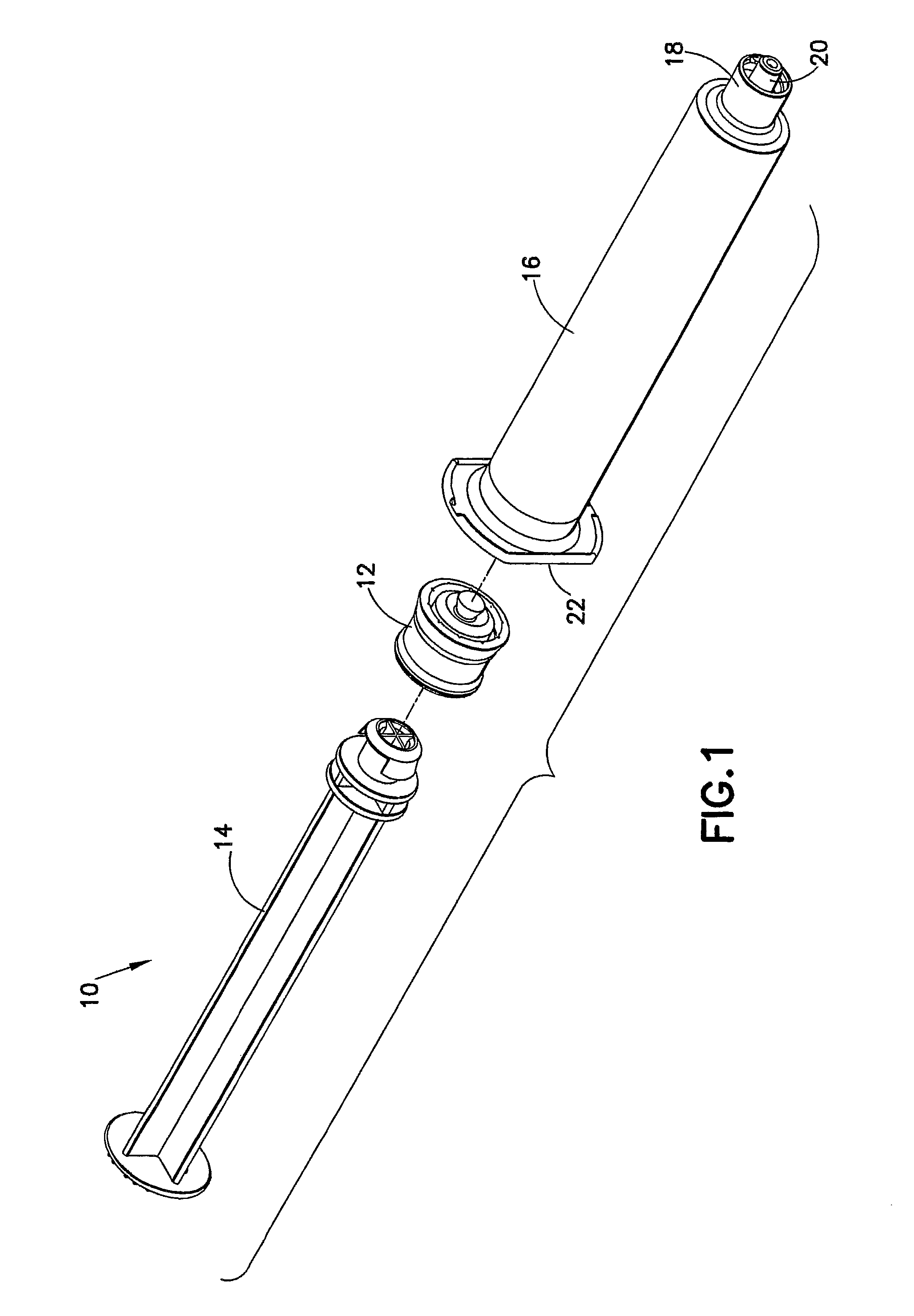
[0009]The particularly disclosed stopper designs create a positive displacement of fluid out of the syringe (and therefore into any attached catheter, for example) after the stopper has been bottomed in the syringe barrel and force is released from the plunger rod so as to effectively and consistently reduce and / or eliminate reflux of fluid back into the syringe upon the release of pressure on the plunger rod. The stopper design also eliminates the possibility of “push through” of the plunger rod within the stopper, shortens the height of the stopper, and improves the moldability. One stopper design also meets the ISO standard for dead space while also achieving a “positively zero” (meaning close to zero) reflux. The stopper is adapted for attachment with a plunger rod for use within a syringe barrel.
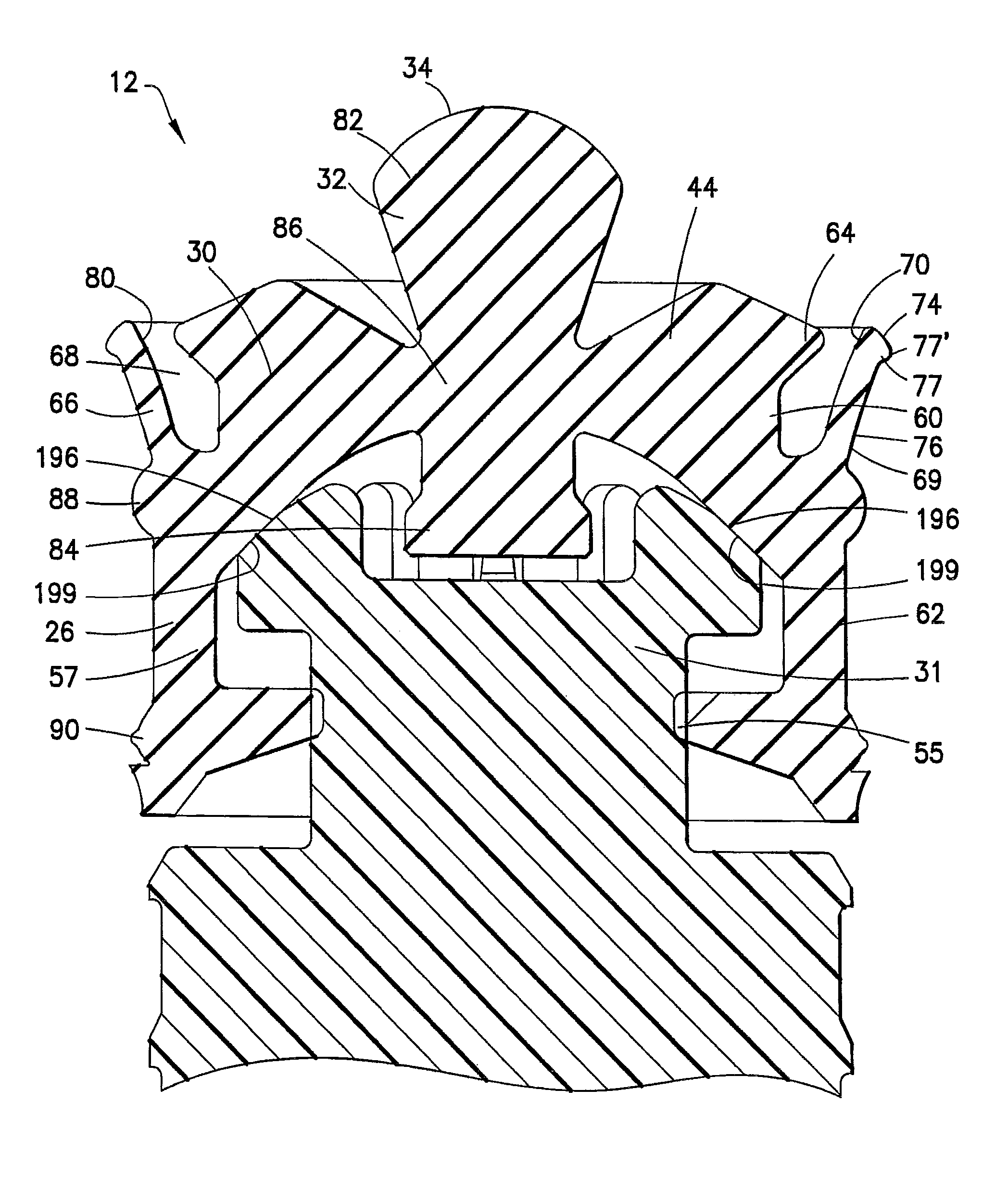
[0010]According to one aspect, the invention is directed to a stopper adapted for attachment with a plunger rod for use within a syringe barrel. The stopper comprises a main body defining an open rearward end and a closed front end. The open rearward end is adapted to receive a front forward end attachment portion of a plunger rod. The stopper also includes a core member integrally formed with the main body adjacent the closed front end. The core member includes a nose portion having a profile adapted to create a positive seal with an outlet opening of the syringe barrel. The stopper includes at least one rib extending radially outward around a perimeter of the main body for forming an active seal with the syringe barrel. An inward shoulder portion is provided on an inner surface of the main body. This inward shoulder portion is adapted for contact with a taper on the forward end of the plunger rod, wherein contact of the inward shoulder portion with the taper causes the stopper to apply a radial force to the at least one rib and the syringe barrel upon the application of a forward force to the plunger rod and wherein the inward shoulder portion includes a first cylindrical wall portion extending from the closed front end of the main body. This first wall portion has a substantially flat surface profile. The inward shoulder portion further includes a second cylindrical wall portion extending toward the open rearward end of the main body. A sloped portion extends between the first wall and the second wall. The provision of a first wall having a substantially flat surface profile results in a shorter stopper having an active seal angle which is relatively shallow. The core member includes a front portion, a back portion, and a central portion positioned between the front and back portion wherein the front portion extends beyond the front end of the main body and the central portion is interconnected with the main body via a flexible membrane extending between the core member and the main body. The main body includes at least one forward extending skirt extending from a front end of the main body which is adapted for creating a positive pressure chamber therein. According to one embodiment, the core member can include a back portion and at least one of the back portions of the core and an inner surface of the closed front wall including at least one concentric groove formed therein. The at least one of the back portions of the core member and the inner surface of the closed front wall include stopper material adapted for contacting the front forward end attachment portion of the plunger rod upon an application of forward force to the plunger rod. This stopper material prevents the stopper from slipping forward and reduces the amount of pressure on the center of the stopper member.

Problems solved by technology

Reflux can also pull blood back into the catheter, clogging it.
This phenomenon of reflux may be detrimental to the maintenance of the catheter line.
The disadvantage of this traditional design is that higher contact pressures lead to higher static and dynamic frictional forces.
These designs, while effective in reducing reflux, do not consistently prevent all reflux from occurring.
Further still, many of these designs include a significant amount of dead space volume.

Method used


Image

  • Stoppers used in pre-filled syringes
  • Stoppers used in pre-filled syringes
  • Stoppers used in pre-filled syringes

Examples


first embodiment

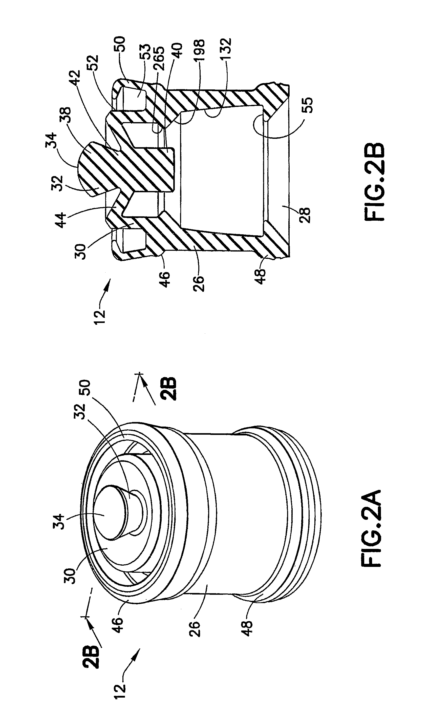
[0080]A feature of the stopper design of the first embodiment illustrated in FIGS. 2A, 2B, and 3 is a forward extending skirt 50 extending from the closed front end 30 of the main body 26. Due to the elasticity and / or flexibility of the forward extending skirt 50, the forward extending skirt 50 is capable of deforming by deflecting radially inwardly toward and substantially in contact with an outer portion 52 of the main body 26. Such deflection may occur upon insertion of the stopper 12 within the syringe barrel 16 to form an air pocket 53 to trap an air bubble therein. The air bubble trapped within air pocket 53 assists in the anti-reflux capabilities of the present invention as discussed in detail below. Upon insertion of the stopper 12 into the syringe barrel 16, the forward extending skirt 50 may be adapted to create a positive pressure within the syringe barrel 16.

[0081]In one embodiment, the main body 26 includes at least one undercut portion 55 extending axially inward from ...

third embodiment

[0085]According to the invention, as illustrated in FIGS. 5A and 5B, an active seal achieves the same result as that of the previously discussed embodiments, but with a different mechanism, commonly referred to as a “lip seal” when used in hydraulic applications. The stopper, generally indicated as 254, includes this lip seal. The front seal 256 of the stopper 254 is located on the leading edge of a flexible arm 258. Initial sealing pressure is generated by the interference of the flexible arm 258 with the wall of the syringe barrel 16, as shown in FIG. 1. When the pressure in the syringe barrel 16 increases, this pressure applies an outward radial force to the inside 259 of the flexible arm 258. This outward force will increase the force with which the seal 256 presses against the inside wall of the syringe barrel 16.

fourth embodiment

[0086]Reference is now made to FIGS. 6A-6F and 7-9 which show the stopper 12 according to the invention. In this embodiment, the stopper 12 includes a main body 26 having a closed front end 30. The main body 26 can include an open rearward end 28 which is adapted to receive a front forward end attachment portion 31 of the plunger rod 14. As stated above, the front forward end attachment portion 31 is capable of attachment to the stopper 12. The main body 26 includes a first body portion 60 having a first diameter D1, as shown in FIG. 6B, and a second body portion 62 having a second diameter D2, as shown in FIG. 6B, which is larger than the first diameter of the first body portion 60. A shoulder 64 extends around a perimeter of the first body portion 60 of the main body 26. Preferably, this shoulder 64 extends in a radially outward direction with respect to the first body portion 60.

[0087]As stated above with respect to the description of the first embodiment, a flexible core member ...


PUM


Abstract

A stopper adapted for attachment with a plunger rod for use within a syringe barrel is disclosed. The stopper includes a main body defining an open rearward end and a closed front end. The open rearward end is adapted to receive a front forward end attachment portion of the plunger rod. The stopper also includes a core member integrally formed with the main body adjacent the closed front end. The core member includes a nose portion having a conical tip configured for entering an outlet opening of the syringe barrel. The closed front end of the stopper has a profile configured to cooperate with an internal surface of the syringe barrel wall to prevent reflux and reduce dead space within the barrel.

Description

CROSS REFERENCE TO RELATED APPLICATIONS[0001]This application is a continuation-in-part of U.S. patent application Ser. Nos. 12 / 133,041 and 12 / 133,076, both filed Jun. 4, 2008, which claim priority to U.S. Provisional Patent Application No. 60 / 941,851, filed Jun. 4, 2007, entitled “Stopper and Plunger Rod for a Pre-Filled Syringe”, and to U.S. Provisional Patent Application No. 60 / 950,741, filed Jul. 19, 2007, entitled “Positive Displacement Stopper for a Pre-Filled Syringe”, the entire disclosures of all of which are hereby incorporated by reference in their entirety.BACKGROUND OF THE INVENTION[0002]1. Field of the Invention[0003]The invention relates in general to a stopper assembly for use with a syringe and, more particularly, to a stopper assembly having low dead space and essentially zero reflux for use with a pre-filled syringe such as those used in flush applications. The invention also relates to a plunger rod and an attachment member adapted for attachment with a stopper a...

Claims


Application Information

Patent Timeline
Patent Type & Authority Patents(United States)
IPC IPC(8): A61M5/315
CPCA61M2005/31521A61M5/31513A61M5/31511A61M5/31515A61M2005/31523
Inventor QUINN, MICHAEL VINCENTSCHILLER, ERICJU, GANGGUAN, E
Owner BECTON DICKINSON & CO
Learn More