
Digital signal conditioning

a digital signal and conditioning technology, applied in the direction of amplitude demodulation, line-fault/interference reduction, pulse technique, etc., can solve the problems of mismatch between operational units, measurement system performance degradation, measurement time and computational complexity of measurement system implemented using synthetic instrument technology, and performance degradation of classic test equipmen

Active Publication Date: 2014-06-03
BAE SYST INFORMATION & ELECTRONICS SYST INTERGRATION INC
View PDF13 Cites 2 Cited by
  • Summary
  • Abstract
  • Description
  • Claims
  • Application Information

AI Technical Summary

Benefits of technology

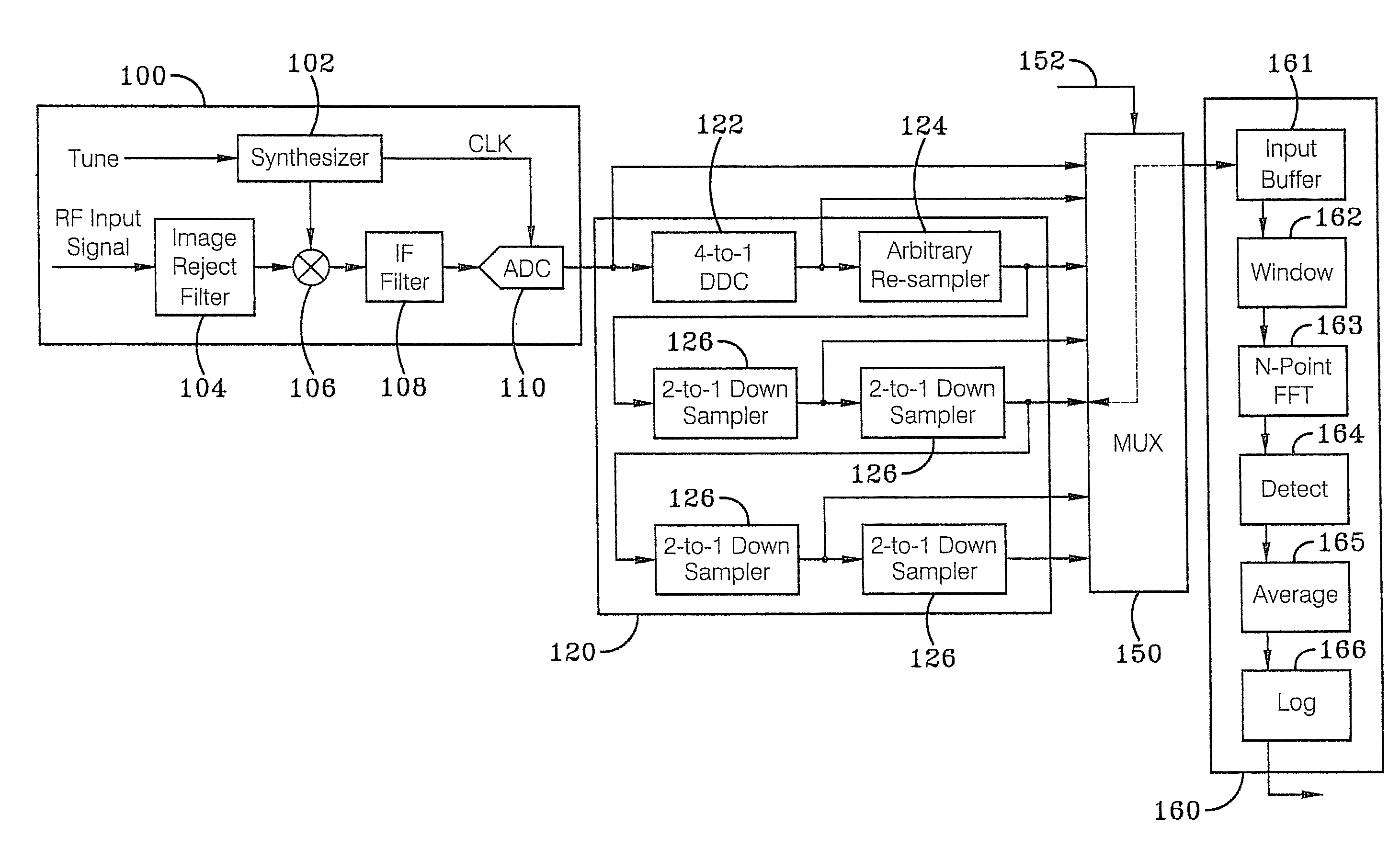
This patent describes a system for processing digital signals. The system includes a digital down converter, interpolator, and series of down samplers. The digital input signal is converted to a lower frequency signal through the digital down converter. The interpolator then re-samples the signal to produce a re-sampled signal. The down samplers produce down sampled signals by taking a series of measurements on the re-sampled signal. A multiplexer selects one of the signals and sends it to an output line. This output line can be connected to a spectrum analyzer input buffer. The system can be configured with different components, such as a 4-to-1 digital down converter and M-path polyphase filter bank with finite impulse response filters and accumulators. The method described in the patent involves down converting an input signal, interpolating it, and then passing it through a series of down samplers to produce down sampled signals, which are multiplexed as an output signal. The technical effects of this system and method include improved signal processing for spectrum analysis.

Problems solved by technology

This dynamic situation often results in a mismatch between the operational units to be supported in the field and the test support systems required to RFI and diagnose these systems.
However, that the precision, accuracy, measurement time and computational complexity of measurement systems implemented using Synthetic Instrument technology may be degraded compared to the performance of classic test equipment.

Method used


Image

  • Digital signal conditioning
  • Digital signal conditioning
  • Digital signal conditioning

Examples


Embodiment Construction

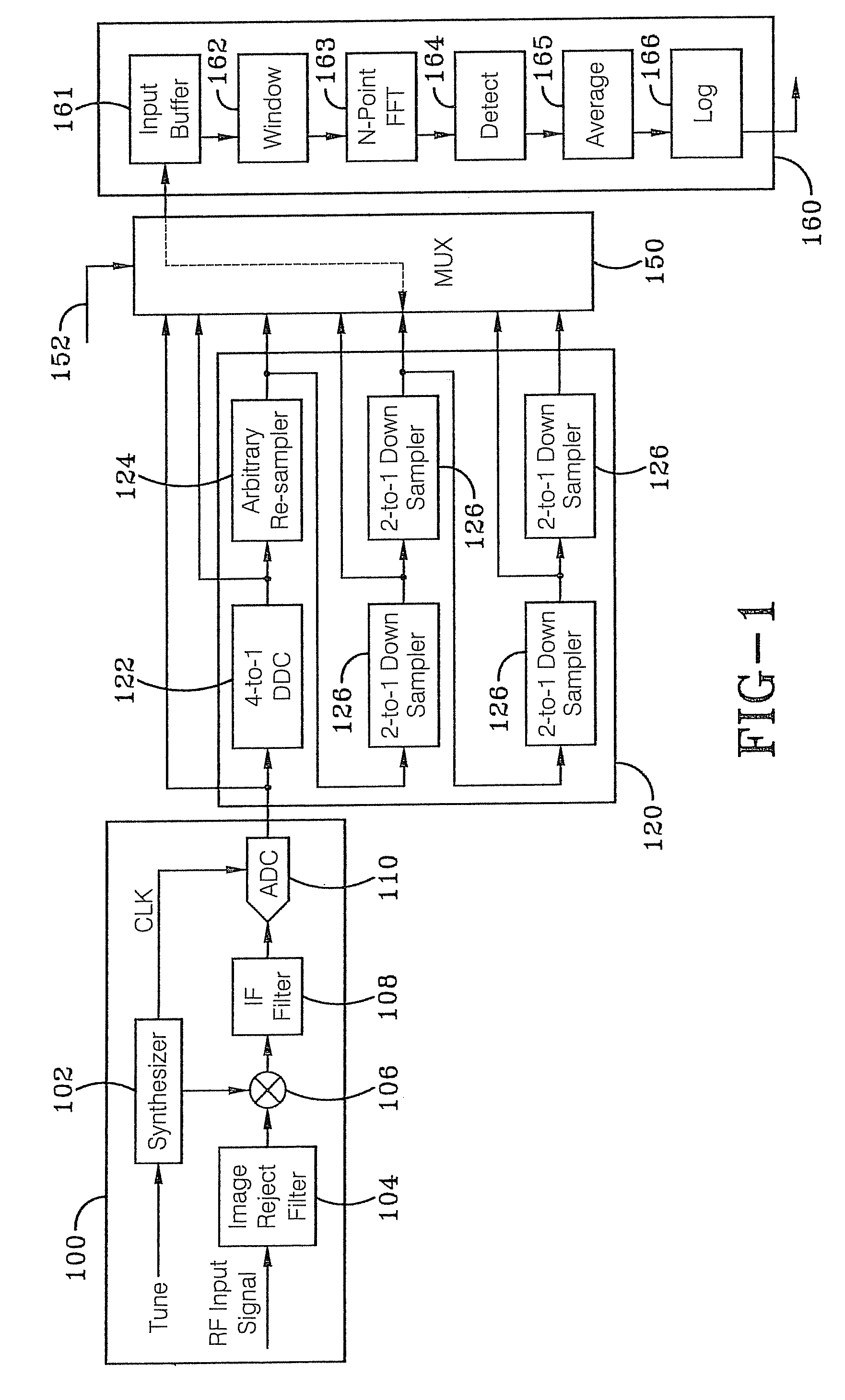
[0023]FIG. 1 illustrates a digital signal processing (DSP) based signal conditioning logic 120 that produces an arbitrary sample rate and arbitrary spectral span of an output from an ADC 110 of an radio frequency (RF) conditioning logic 100. The digitally conditioned signal is provided to the input buffer 161 of a synthetic instrument spectrum analyzer module 160. Those of ordinary skill in the art will appreciate that the RF conditioning logic can include a synthesizer 102, an image reject filter 104, a mixer 106, an intermediate frequency (IF) filter 108 and an analog to digital converter 110, as well as other components. The synthetic instrument spectrum analyzer module 160 can also include window logic 162, N-Point fast fourier transform (FFT) logic 163, detect logic 164, averaging logic 165, logarithmic logic 166, as well as other components.

[0024]In the preferred embodiment, the digital signal conditioning logic 120 includes a digital signal conditioner (DDC) 122, an interpola...


PUM


Abstract

Methods, systems and other embodiments associated with pre-processing a signal for spectral analysis are presented. A system for pre-processing a digital input signal includes a digital down converter (DDC), an interpolator, and a series of down samplers. The DDC modulates the digital input signal to create a down converted signal. The interpolator re-samples the down converted signal to produce a re-sampled signal. The series of down samplers produces down sampled signals. The multiplexer selects one of the digital input signal, the down converted signal, and the down sampled signals and routes the selected signal to an output line.

Description

CROSS REFERENCE TO RELATED APPLICATIONS[0001]This application claims priority from PCT Patent Application No. PCT / US2010 / 047074, filed Aug. 30, 2010 which claims priority from U.S. Provisional Patent Application Ser. No. 61 / 238,235, filed Aug. 31, 2009; the disclosures of which are incorporated herein by reference.BACKGROUND OF THE INVENTION[0002]1. Technical Field[0003]The present invention relates generally to apparatus and systems for signal processing. More particularly, the apparatus and systems related to digital signal processing. Specifically, the apparatus and systems of the present invention relate to digital conditioning of a signal with a pre-processing engine.[0004]2. Background Information[0005]Spectrum analysis of an input signal is one of the most common processing tasks of a Synthetic Instrument (SI). Instruments that perform spectrum analysis have evolved over the years from parallel filter bank implantations through sequential swept frequency implementations to mo...

Claims


Application Information

Patent Timeline
Patent Type & Authority Patents(United States)
IPC IPC(8): H04B1/10
CPCG01R23/16
Inventor LOWDERMILK, ROBERT W.VULETIC, DRAGANHARRIS, FREDRIC J.TAMMEN, MICHAEL
Owner BAE SYST INFORMATION & ELECTRONICS SYST INTERGRATION INC
Learn More