Method and system for automatic objects localization

a technology object localization, applied in the field of automatic object localization, can solve the problems of complex automatic object localization, high hardware cost, etc., and achieve the effect of being flexible with respect to heterogeneous camera networks

Inactive Publication Date: 2014-06-10
ECOLE POLYTECHNIQUE FEDERALE DE LAUSANNE (EPFL)
View PDF10 Cites 16 Cited by
  • Summary
  • Abstract
  • Description
  • Claims
  • Application Information

AI Technical Summary

Benefits of technology

[0023]One object of the present invention is to provide a method and a system for detecting / localizing objects, robust to noise, to possible occlusions of objects and to abrupt changes of the scene.
[0038]Advantageously the system for detecting objects according to the invention is scalable to any number of used cameras, including a single camera setup, and versatile with respect to heterogeneous camera network. It does not require large memory storage.

Problems solved by technology

The main difficulty in automatic localization of the objects comes from the mutual occlusions of these objects in a group.
The most effective techniques in the related art for detecting moving people or objects occluding each other are highly complex and may thus require the use of costly hardware.
Moreover, they may not be fast enough to perform in real-time detection and localization of people or objects within a crowd.
This method does not work by using a single camera with fixed orientation.
Such an approach is computationally intensive.
Moreover, the higher the accuracy of representation of the foreground silhouette shape to be matched, the more complex the calculations are.
Current approaches fail to robustly isolate different persons in the image of a group of people taken by one camera due to their mutual occlusions.
However, current multi-view approaches do not robustly segment a crowd of people.
This mathematical framework leads to potentially high false positives rate.
In addition, the computation cost of the algorithm depends on the number of ground plane points to be evaluated, which limits the area to be monitored.
Moreover, this algorithm does not work in real-time.

Method used


Image

  • Method and system for automatic objects localization
  • Method and system for automatic objects localization
  • Method and system for automatic objects localization

Examples


Embodiment Construction

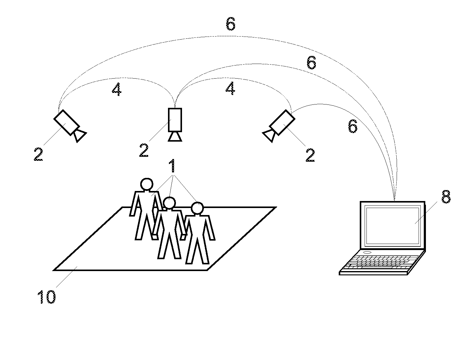
[0050]FIG. 1 illustrates one embodiment of a system for detecting / localizing objects according to the invention. It comprises at least one or several cameras 2. The camera may be either analog or digital. If an analog device is used, the image is digitalized with means known by the man skilled in the art. The camera 2 can be planar and / or omnidirectional. In one embodiment IR cameras can be used. The cameras 2 can have overlapping field-of-views. Moving camera can also be used instead or in addition to static camera.

[0051]In the example of FIG. 1, there are three static cameras 2. When at least two cameras are used, they are pseudo-synchronized, in order to acquire quasi simultaneously images. In this application with the expression “cameras pseudo-synchronized” it is intended cameras that acquire images that are not precisely simultaneous but that can be considered as simultaneous, i.e. having a few frame delay, a few ms of difference. Cameras 2 are connected to an image processing...


PUM


Abstract

A method for automatic localization of objects in a mask. The method includes building a dictionary of atoms, wherein each atom models the presence of one object at one location and iteratively determining the atom of said dictionary which is best correlated with said mask, until ending criteria are met. The invention system concerns also automatically detects objects in a mask. At least one fixed camera is provided for acquiring video frames. A computation device is used for calibrating at least one fixed camera for extracting foreground silhouettes in each acquired video frames for discretizing said ground plane into a non-regular grid of potential location points for constructing a dictionary of atoms, and, for finding objects location points with the previous method. And a propagating device is provided to propagate the result in at least one fixed camera view.

Description

FIELD OF THE INVENTION[0001]The present invention concerns a method and a system for automatic localization and / or detection and / or identification and / or singulation and / or segmentation and / or computation and / or tracking of objects. More precisely, objects are automatically detected and localized on the ground and in the image planes of a network of cameras or even a single camera setup. Objects can be people in a crowded environment.DESCRIPTION OF RELATED ART[0002]Accurate vision-based people detection has been of interest for the past decades in many applications. A number of surveillance applications for example require the detection of people to ensure security, safety and site management. Examples include the behavior analysis and the monitoring of entry points, bus terminal and train stations in order to know for example if people stay in a forbidden area.[0003]Another example is the safety in an urban environment: the knowledge of the pedestrians' positions can for example pr...

Claims


Application Information

Patent Timeline
Patent Type & Authority Patents(United States)
IPC IPC(8): H04N7/18G06V20/00
CPCG06K9/00785G06T7/0044G06T2207/10004G06T7/0079G06K9/00778H04N7/18H04N5/247G06T2207/30196G06T2207/30232H04N5/33G06K9/00771G06K9/00624G06T2207/20144G06T2207/10016G06V20/00G06V20/54G06V20/52G06V20/53H04N23/90
Inventor ALAHI, ALEXANDREGOLBABAEE, MOHAMMADVANDERGHEYNST, PIERRE
Owner ECOLE POLYTECHNIQUE FEDERALE DE LAUSANNE (EPFL)
Why Eureka
Try Eureka