Blender air intake snorkel for countertop or in-counter installations

a technology for countertop or in-counter installations, which is applied in the direction of juice extraction, indirect heat exchangers, lighting and heating apparatus, etc. it can solve the problems insufficient cooling air moving, and inefficient cooling systems of existing appliances, so as to reduce noise, reduce the possibility of contaminating the blender motor housing, and reduce the effect of air flow

Active Publication Date: 2014-06-17
HAMILTON BEACH BRANDS
View PDF14 Cites 15 Cited by
  • Summary
  • Abstract
  • Description
  • Claims
  • Application Information

AI Technical Summary

Benefits of technology

[0009]A blender with an air intake snorkel for countertop or in-counter installations is provided. The air intake snorkel provided herein reduces noise, creates an efficient air flow, and reduces the possibility of contaminating a blender motor housing with fluids or food stuff. The result is an improved cooling system for blender electric motor housings.
[0014]In one embodiment, the snorkel further comprises a protective cap adjacent the intake opening. The cap is operable to shield the intake opening from, or reduce the possibility of, contamination from fluid, food, or other foreign objects. The cap partially obstructs access to the intake opening while allowing an air flow past the cap and into the intake opening. Air flow caused by operation of the fan causes the fluid movement of cooling air through the snorkel conduit to the outlet opening, inlet aperture, and air passageway. With the optional cap in place, and in one preferred embodiment, an upward, vertical air flow is created prior to the air entering the intake opening. Specifically, cooling air moves upwards between the snorkel body and cap before entering the intake opening. The vertical air flow reduces the possibility of vacuuming solids or fluids from the space proximate to the intake opening.
[0015]In another preferred embodiment, the conduit first extends roughly or generally horizontally away from the motor housing. An elbow or corner turns the conduit vertically. Therefore, the intake opening is facing vertically (i.e., entry to the intake opening occurs along a vertical axis), and the optional cap at least partially covers the intake opening. Air is pulled upwards past the cap before passing through the intake opening, moving down and then laterally through the conduit, and exiting the conduit via the outlet opening. The conduit is internally rounded at the elbow or juncture to create smooth / quite air flow.
[0016]A blender intake snorkel in accordance with the disclosure herein efficiently addresses at least one of the above or other identified shortcomings associate with existing blender air intake structures. For instance, extending the air intake away from (and / or upwards from) the motor housing provides fresher / cooler air compared to standard blender intakes. In a preferred embodiment, the housing is cubical in that it has four substantially vertical walls, a top side, and bottom side, the top and bottom sides enclosing the space between the four substantially vertical walls. The intake opening is located in the plane of the top wall (‘in-plane’) or above the top side of the blender base (i.e., above the plane defined by the top side of the housing). The re-circulation of warm exhaust air through the motor housing is reduced relative to conventional blenders. The placement of the intake opening is thought to draw cooler air into the blender relative to an intake opening or inlet aperture located beneath the top side of the blender. The location of the intake opening reduces or eliminates the possibility of food, drink or other contaminants being vacuumed by the fan into the housing.
[0017]In addition, the snorkel is operable with a countertop or in-counter installation of the blender. With a standard air intake design, an in-counter installation could mean the intake is near or below the countertop level. The air intake snorkel as disclosed herein moves the intake above and away from the countertop for cooler air with a lower probability of contaminating the appliance motor housing. A cap prevents against the accidental entry of solids or fluids entering from a point above the intake opening. In addition, the cap creates a vertical air flow that reduces the possibility of vacuuming solids or fluids from points proximate to the intake opening.

Problems solved by technology

Unfortunately, many existing appliance cooling systems are inefficient.
This commonly occurs because the appliance, including blenders, moves an insufficient volume of cooling air due to vents of inadequate surface area.
Typical air intakes are often located in close proximity to an exhaust outlet resulting in recirculation of hot air.
These inefficiencies may result in reduced cooling.
In addition to cooling the motor, the inefficient air flow and fan operation creates noise.
An inefficient air flow particularly can create a substantial noise level.
If an engineer tries to compensate for the poor cooling of a motor with a more powerful fan, then the result is to create even more noise.
Perhaps the most difficult challenge to increasing appliance motor cooling efficiency is the placement of the air intake and exhaust outlet.
This is particularly true as more blenders incorporate complicated electronic controls and components.
The proximity or location of the air intake to the exhaust outlet often causes warm exhaust air to be recirculated into the motor chamber thereby greatly reducing the appliance's cooling efficiency.
Typical blenders are also not constructed with in-counter installations in mind (i.e., a portion of the blender extends into or through the plane defined by a countertop), and they are certainly not designed with both countertop and in-counter installations in mind.
Therefore, current blender air intake and outlet assemblies are not conducive to, or would preclude, in-counter appliance installations.
When a conventional blender is installed in-counter, the typical ‘grate’-style air intake is moved to a point immediately proximate to the countertop's upper surface, which only increases the possibility of contamination.
A sub-countertop air intake is thought to be detrimental as the space under a countertop can contain warm, recirculated, and / or stagnant air that could impede motor cooling.

Method used


Image

  • Blender air intake snorkel for countertop or in-counter installations
  • Blender air intake snorkel for countertop or in-counter installations
  • Blender air intake snorkel for countertop or in-counter installations

Examples


Embodiment Construction

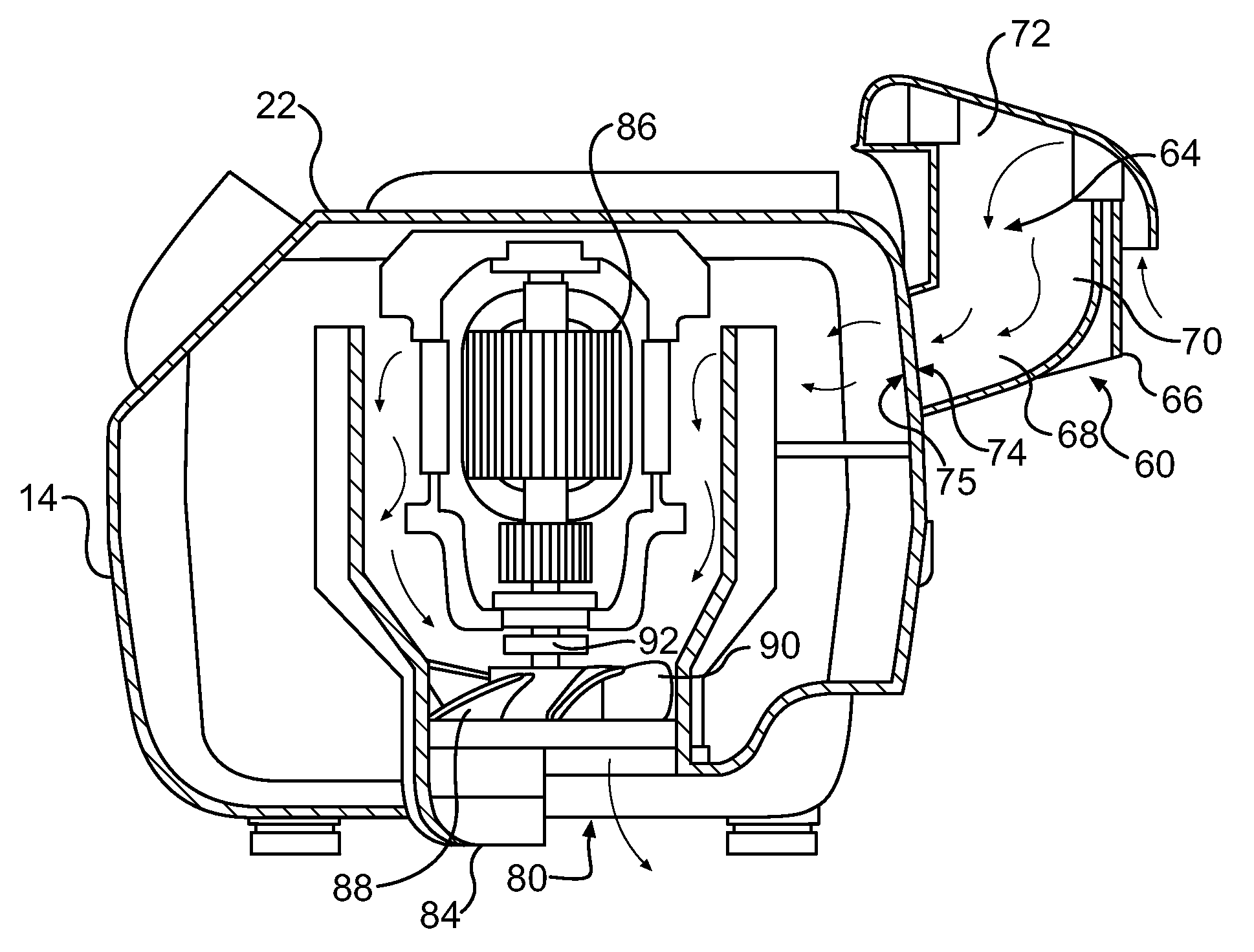
[0026]As will be described in detail herein, the supply of an air flow through a blender motor housing (a.k.a., a ‘blender base’) can be improved by an air intake snorkel to increase cooling effect, reduce noise, and reduce or eliminate contamination of the air intake. An air intake snorkel may also be designed for selective countertop and in-counter installations of the same blender. The possible variations of the snorkel are adaptable for use with many existing motor housings. Accordingly, the specific structure disclosed should not and is not a reasonable limitation of the scope of the present invention. The following describes certain preferred embodiments of an air intake snorkel and a blender with such a snorkel.

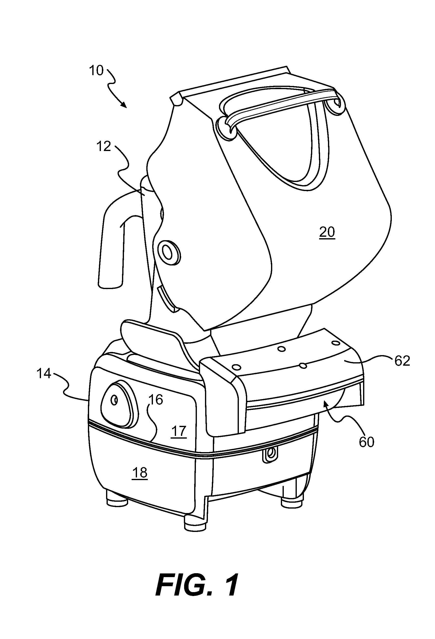
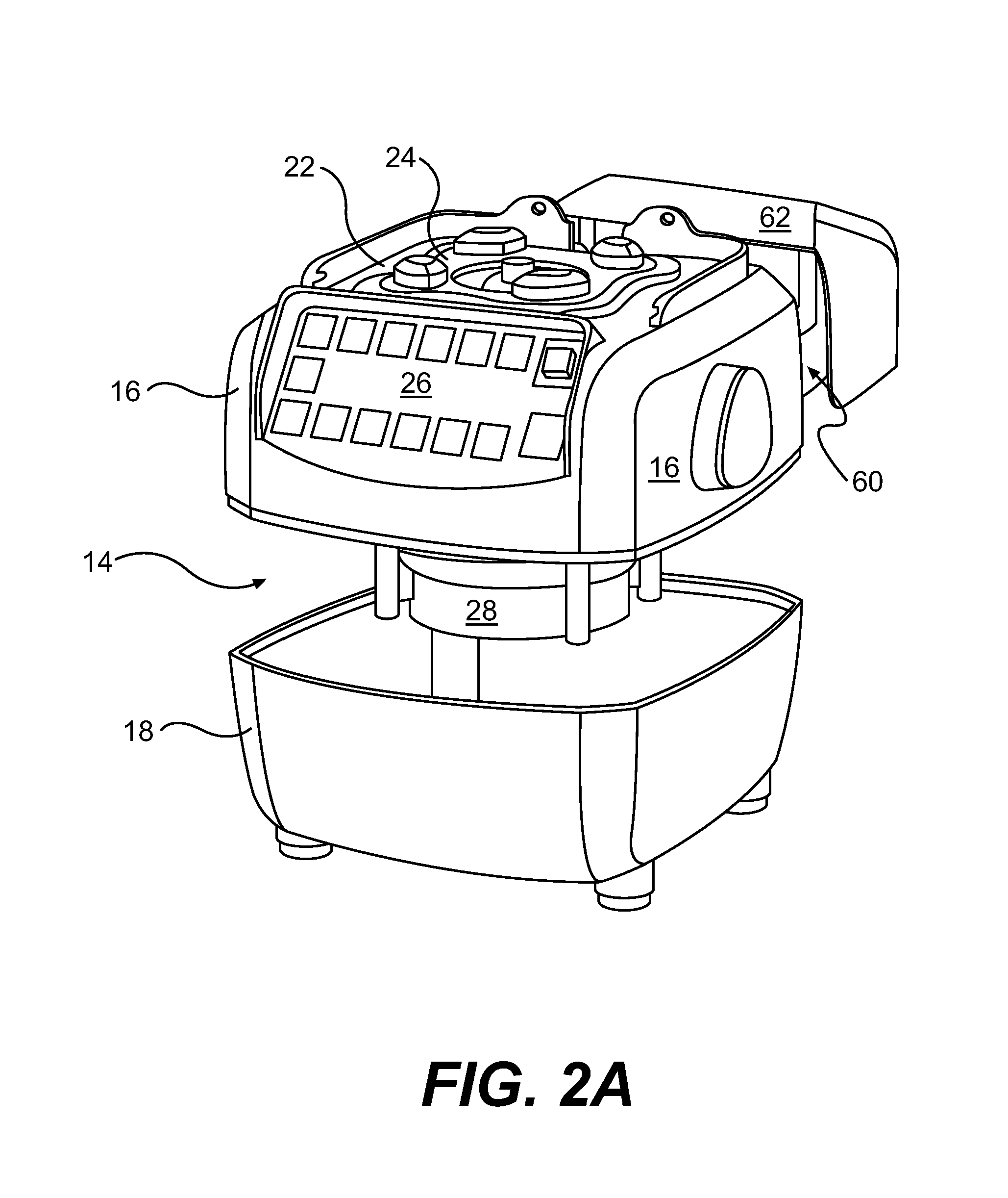
[0027]Turning first to FIG. 1, there is illustrated a blender 10 having a blender jar 12 mounted onto the blender base or motor housing 14. Housing 14 may be an integral, one-piece shell to enclose a motor and the corresponding appliance electronics. The specific shape...


PUM


Abstract

A blender with an air intake snorkel where the snorkel extends away from a motor housing provided by the blender is provided. The snorkel includes an air intake opening, an outlet opening, and a conduit fluidly connecting the intake and outlet openings. In one preferred embodiment, the snorkel includes a cap connected to the snorkel wherein the cap partially obstructs access to the intake opening in order to prevent contamination of the conduit. The outlet opening fluidly communicates with an inlet aperture provided by the motor housing. In use, an electric motor contained by the housing actuates a fan. The fan pulls air through the intake opening, conduit, and outlet opening. The air enters the housing via the inlet aperture where it acts to cool the electric motor. In one preferred embodiment, the appliance is a blender and the motor housing comprises a blender base that is installed on a countertop or in-counter (i.e., a portion of the blender extends into or through the plane defined by a countertop). The air intake snorkel reduces contamination of the interior of the appliance, provides efficient airflow for motor cooling, and reduces the re-circulation of warm appliance exhaust air into the motor housing.

Description

[0001]The present invention relates to a blender air intake for countertop or in-counter blender installations wherein the air intake extends away from the body of the blender. More specifically, the blender air intake as disclosed herein provides a snorkel function in that the intake supplies cool, dry air drawn from a point away from the blender's motor housing, and the air is operable to cool an appliance motor.BACKGROUND OF THE INVENTION[0002]Kitchen countertop appliances incorporate electric motors operable to slice, dice, crush, mix, blend or otherwise process food and drink products. The motors, generally operating at speeds of thousands to tens of thousands of rotations per minute, must be cooled to operate efficiently. Typically, electric appliance motors are cooled by a fan integral to the motor wherein the fan blows air on or draws air over the motor during operation. Unfortunately, many existing appliance cooling systems are inefficient. This commonly occurs because the ...

Claims


Application Information

Patent Timeline
Patent Type & Authority Patents(United States)
IPC IPC(8): A23N1/00
CPCA47J43/085
Inventor WILLIAMS, BRIAN PAULASHWORTH, STEVEN W.
Owner HAMILTON BEACH BRANDS
Why Eureka
Try Eureka