

Ground rodent repeller
a ground rodent and battery technology, applied in the field of ground rodent repellers, can solve the problems of high production cost, complicated and time-consuming battery replacement procedure of groundhog repellers, and affecting the operation of electric vehicles, and achieve the effects of low production cost, easy installation, and simple assembly
- Summary
- Abstract
- Description
- Claims
- Application Information
AI Technical Summary
Benefits of technology
Problems solved by technology
Method used
Image

Examples
first embodiment
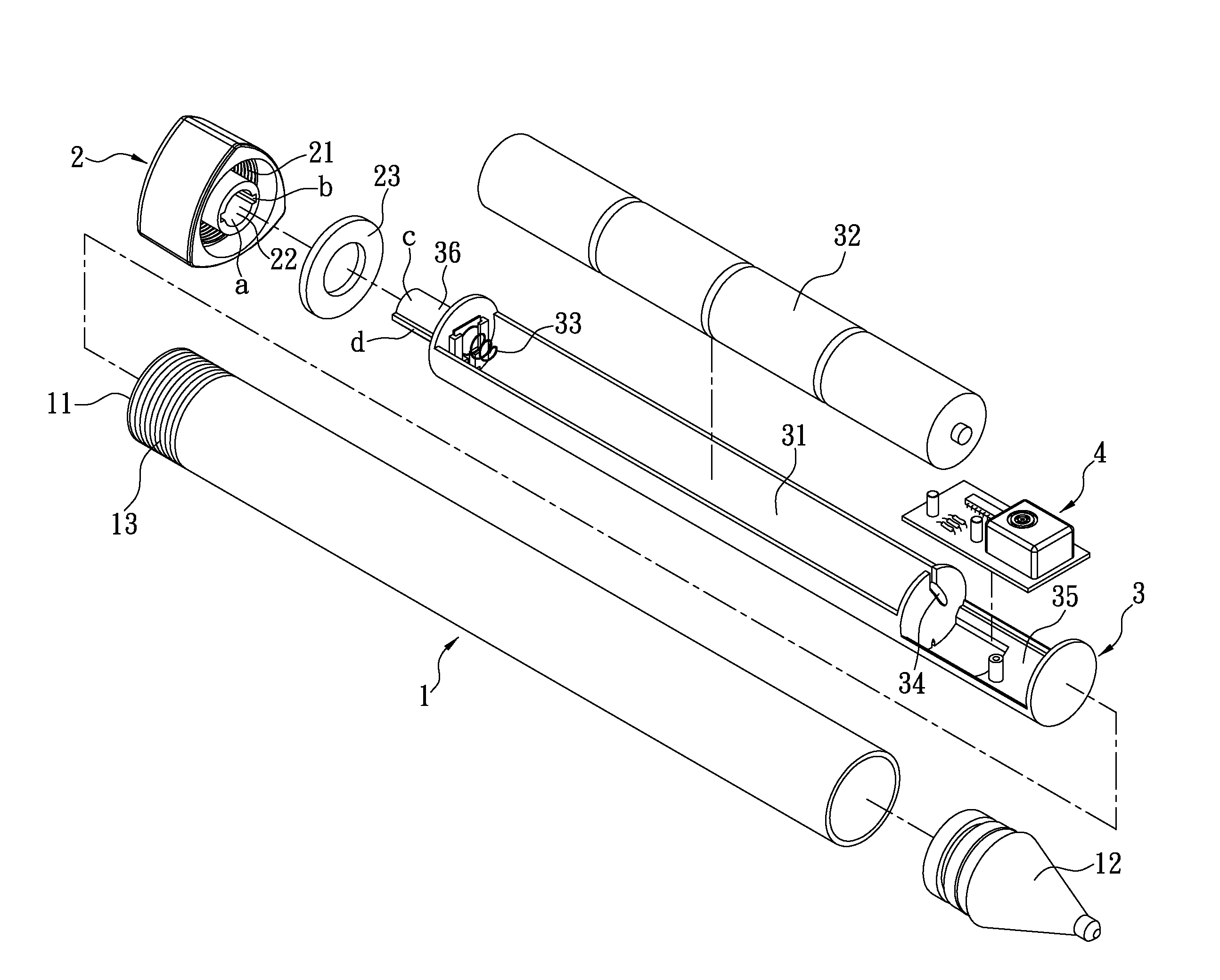
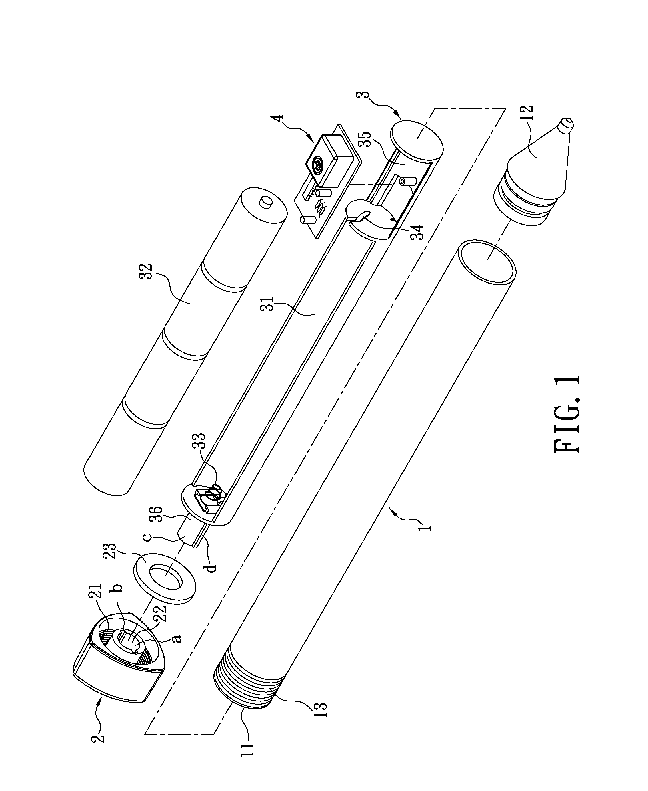
[0024]Referring to FIG. 1 to FIG. 4, the present disclosure provides a ground rodent repeller, including a main rod 1, a cover 2, a battery base 3 and a control circuit board 4. The main rod 1 is a hollow rod, ideally but not necessarily made out of metal. The shape of the main rod 1 is likewise not limited, and can be for example a circular cylinder or other cylinders. An opening 11 is formed on a (top) end of the main rod 1, for the battery base 3 and the control circuit board 4 to be disposed through into the main rod 1.
[0025]A pointed end 12 can be formed on the other (bottom) end of the main rod 1, for inserting into the ground. The pointed end 12 can be integrated as one body with the main body 1 on the other end, or can be connected by assembly to the other end of the main rod 1. The end of the main rod 1 with the opening 11 formed thereon has a first screw thread 13. The first screw thread 13 can be a male thread or a female thread. The first screw thread 13 disclosed in the...
second embodiment
[0038]Referring to FIG. 5, in the present embodiment, a retaining structure 5 is further disposed between the first locking part 22 and the second locking part 36, for retaining the first locking part 22 to the second locking part 36. The retaining structure 5 can include a concave part 51 disposed on the first locking part 22 and a convex part 52 disposed on the second locking part 36. The concave part 51 and the convex part 52 engage with each other, for providing a retaining by engagement effect such that the cover 2 can be securely connected to one end of the battery base 3. In another embodiment, the retaining structure 5 includes a convex part of the first locking part 22 (not shown in the figure) and a concave part of the second locking part 36 (not shown in the figure). The convex part and the concave part engage with each other, likewise achieving a retaining by engagement effect.
third and fourth embodiments
[0039]Referring to FIG. 6 and FIG. 7, the present embodiments disclose that the first locking part 22 is a locking groove A with the shape of a polygonal cylinder (such as a tetragonal, pentagonal, or hexagonal cylinder). The present embodiments disclose that the second locking part 36 is a locking body C with the shape of a polygonal cylinder (such as a tetragonal, pentagonal, or hexagonal cylinder). The first locking part 22 (locking groove A) of the cover 2 and the second locking part 36 (locking body C) of the battery base 3 engage with each other, such that the cover can be connected by engagement to one end of the battery base 3.
PUM
 Abstract
Description
Claims
Application Information