
Electrostatic transducer loudspeaker

a technology of electrostatic transducer and loudspeaker, which is applied in the direction of electrostatic transducer, electrical transducer, electrostatic transducer loudspeaker, etc., can solve the problems of unavoidably increasing the volume and cost of physical devices, bulky physical devices, and high cos

Inactive Publication Date: 2014-06-17
RICHTEK TECH
View PDF2 Cites 3 Cited by
  • Summary
  • Abstract
  • Description
  • Claims
  • Application Information

AI Technical Summary

Benefits of technology

The present invention is a filterless electrostatic transducer loudspeaker. It includes a class-D amplifier, a transformer, and an electrostatic transducer. The amplifier modulates an audio input signal to remove a pulse width modulation switching carrier component, which is then removed by the transformer. This results in an AC voltage that can drive the electrostatic transducer without using any filter. The technical effect is to provide a more efficient and effective loudspeaker that can demodulate the modulated signal using the resonant circuit of the transformer and electrostatic transducer.

Problems solved by technology

However, the low-pass filter unavoidably increases the volume and cost of the physical device.
On the other hand, the conventional electrostatic transducer needs a very high direct current (DC) bias voltage, and thus requires a power supply circuit capable of providing the high DC voltage, thereby causing the resultant physical device bulky and costly.

Method used


Image

  • Electrostatic transducer loudspeaker
  • Electrostatic transducer loudspeaker
  • Electrostatic transducer loudspeaker

Examples


Embodiment Construction

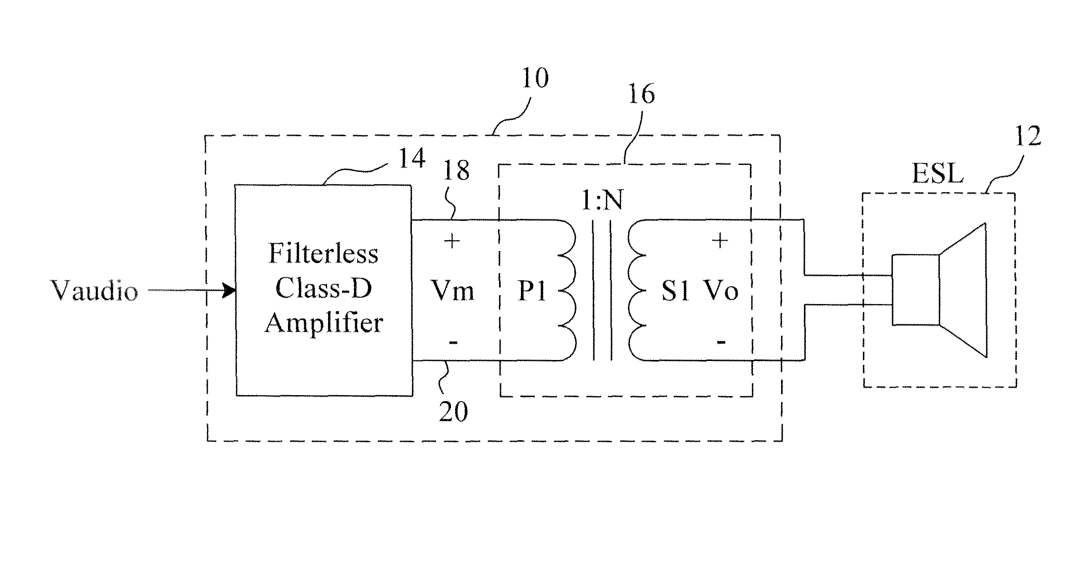
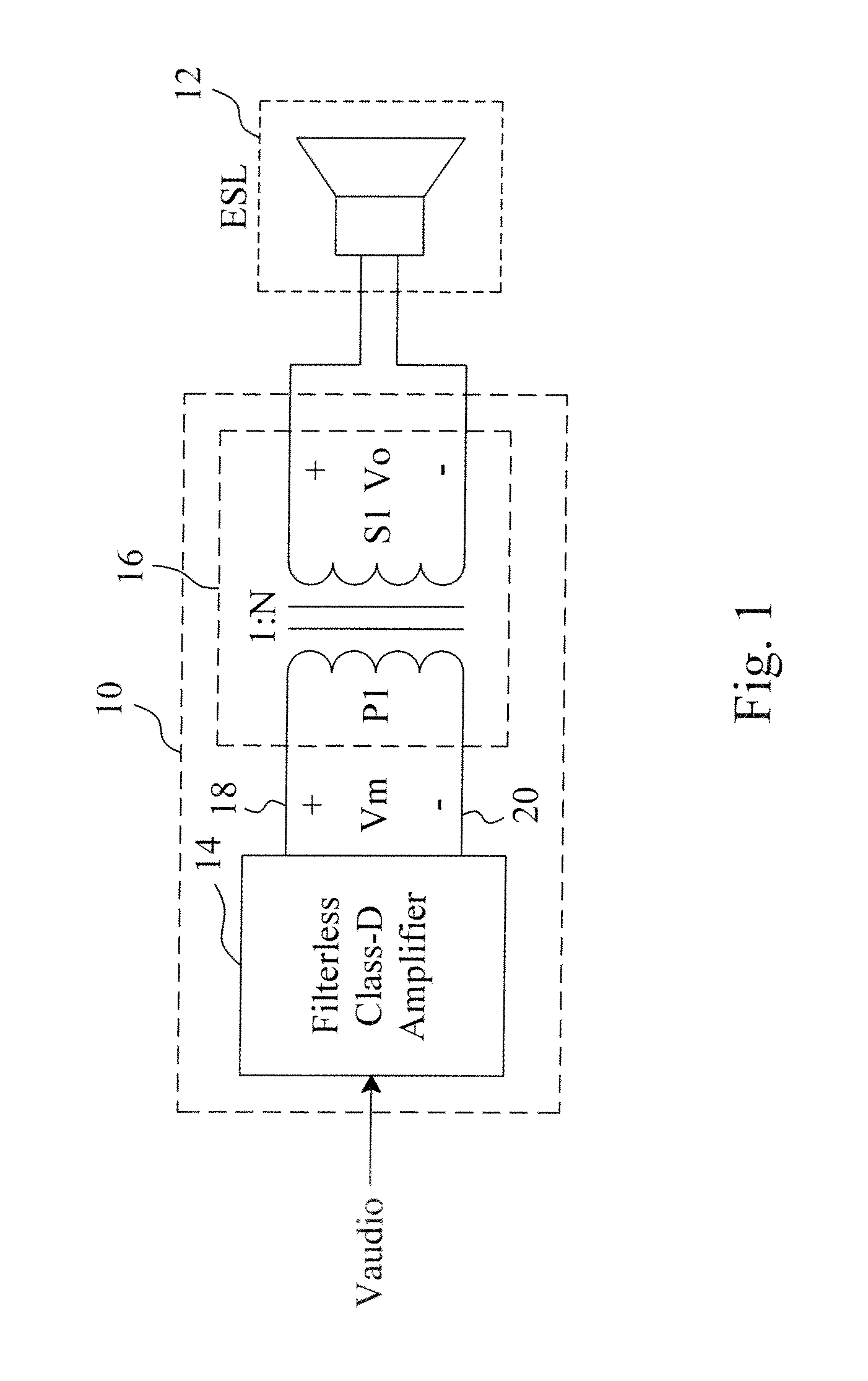
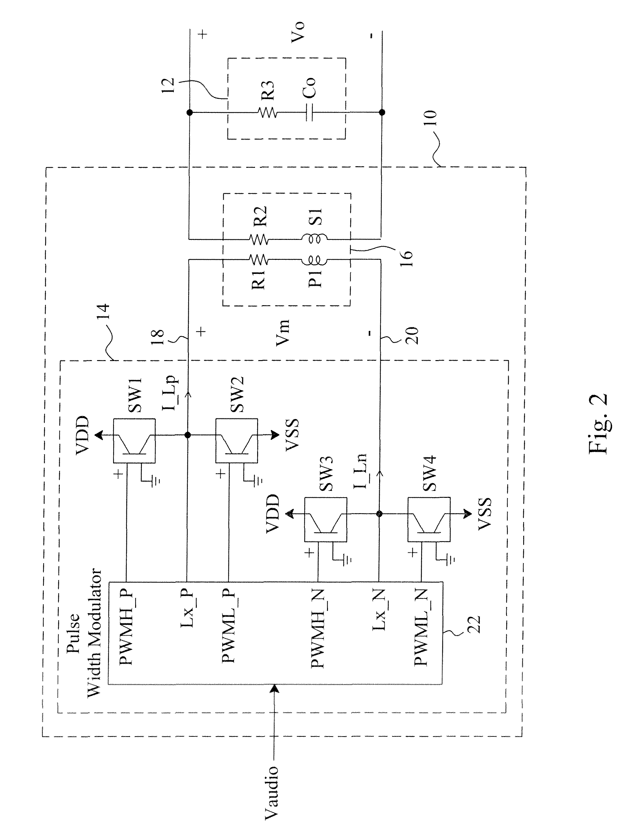
[0010]FIG. 1 shows an electrostatic transducer loudspeaker according to the present invention, which includes a driving circuit 10 and an electrostatic transducer 12 driven by the driving circuit 10. The electrostatic transducer 12 needs no provision of DC bias voltage and is capable of being directly driven by an alternative current (AC) signal. Readers may refer to U.S. Patent Application Publication No. 2009 / 0016551 for detailed structure and principle of an electrostatic transducer. In the driving circuit 10, a filterless class-D amplifier 14 modulates the audio input signal Vaudio to generate a modulated signal Vm containing a PWM switching carrier component, a transformer 16 has a primary coil P1 directly connected to the output terminals 18 and 20 of the filterless class-D amplifier 14 and a secondary coil S1 directly connected to the input terminals of the electrostatic transducer 12. In this architecture, there is no filters between the transformer 16 and the filterless cla...


PUM


Abstract

An electrostatic transducer loudspeaker includes a filterless class-D amplifier to modulate an audio input signal to generate a modulated signal containing a PWM switching carrier component, and a transformer directly connected at an output side of the filterless class-D amplifier and directly connected at an input side of an electrostatic transducer, whereby the equivalent capacitance of the electrostatic transducer and the equivalent inductance of the transformer establish a resonance circuit to demodulate the modulated signal to generate an AC voltage to drive the electrostatic transducer.

Description

FIELD OF THE INVENTION[0001]The present invention is related generally to an electrostatic transducer loudspeaker and, more particularly, to a filterless electrostatic transducer loudspeaker.BACKGROUND OF THE INVENTION[0002]U.S. Patent Application Publication No. 2007 / 0121970 discloses an electrostatic transducer whose driving circuit uses a class-D amplifier, and the output of the class-D amplifier is necessarily coupled with a low-pass filter to eliminate the switching carrier components included in the output signal of the class-D amplifier. However, the low-pass filter unavoidably increases the volume and cost of the physical device. While exactly helping to reduce the volume and cost of a physical device, a filterless class-D amplifier is only applicable to inductive transducers. On the other hand, the conventional electrostatic transducer needs a very high direct current (DC) bias voltage, and thus requires a power supply circuit capable of providing the high DC voltage, there...

Claims


Application Information

Patent Timeline
Patent Type & Authority Patents(United States)
IPC IPC(8): H04R3/00
CPCH04R3/00H04R19/005H03F3/217H04R3/002H04R19/02
Inventor HUANG, PEI-CHENGGUO, JWIN-YEN
Owner RICHTEK TECH
Learn More