Active fixation medical electrical lead

a technology of medical electrical leads and active fixation, which is applied in the field of implantable medical electrical leads, can solve problems such as interference with removal

Active Publication Date: 2014-06-17
MEDTRONIC INC
View PDF11 Cites 35 Cited by
  • Summary
  • Abstract
  • Description
  • Claims
  • Application Information

AI Technical Summary

Benefits of technology

[0021]A lead according to the present invention includes an additional component to accomplish the desired result. The additional component is located adjacent the point at which the fixation mechanism extends from the lead body and in conjunction with the fixation mechanism and lead body defines a relatively blunt-ended recess. When the fixation mechanism is inserted into body tissue, the additional component serves to limit the extent to which the fixation mechanism penetrates the tissue and additionally limit the degree to into which the tissue is compressed between the fixation mechanism and the lead body. This in turn, prevents wedging of the tissue between the fixation mechanism and the lead body and facilitates removal of the lead without damage to the body tissue.

Problems solved by technology

The inventors have determined that such wedging can interfere with removal of the lead.

Method used


Image

  • Active fixation medical electrical lead
  • Active fixation medical electrical lead
  • Active fixation medical electrical lead

Examples


Embodiment Construction

[0023]The following detailed description is exemplary in nature and is not intended to limit the scope, applicability, or configuration of the invention in any way. Rather, the following description provides practical illustrations for implementing exemplary embodiments of the present invention. Constructions, materials, dimensions, and manufacturing processes suitable for making embodiments of the present are known to those of skill in the field of the invention.

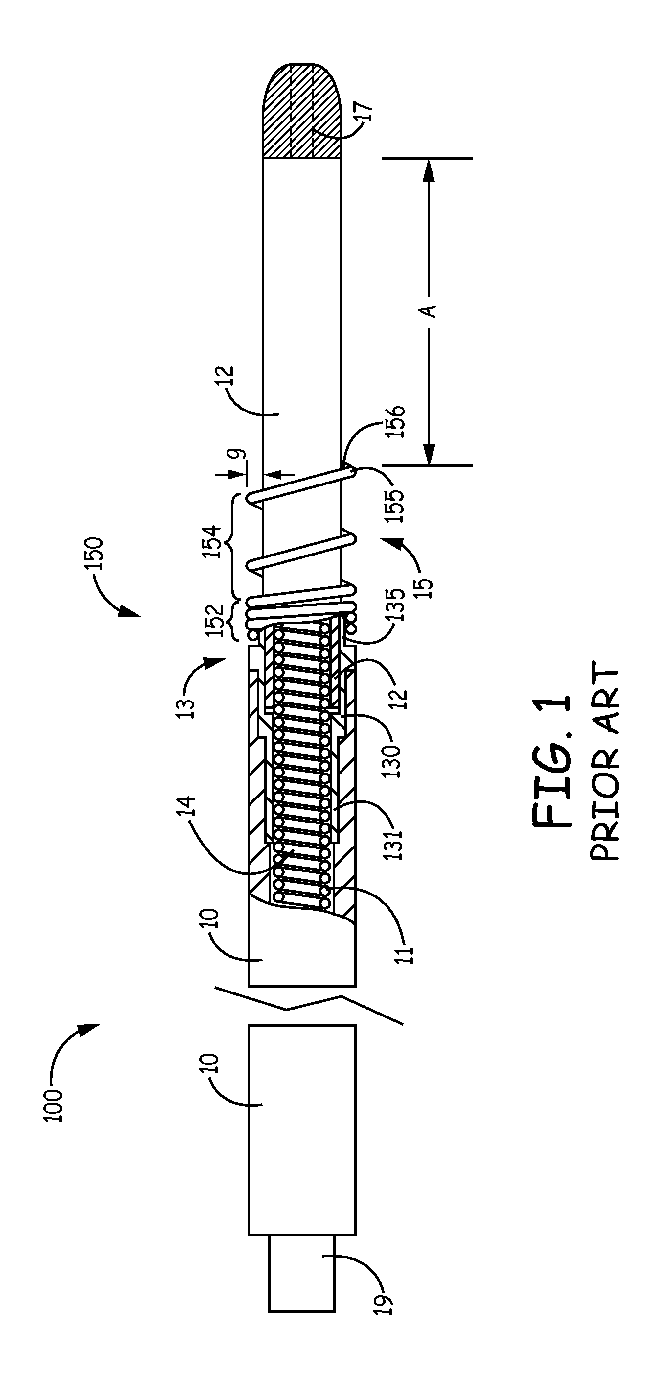
[0024]FIG. 1 is a plan view, including a partial section, of an electrical lead 100, according to the prior art, to which the present invention may be added. FIG. 1 illustrates lead 100 including a proximal connector pin 19, a distal tip electrode 17, and an elongate conductor 11, for example, a multi-filar coil formed from MP35N alloy, which couples connector pin 19 to electrode 17. Connector pin 19 may be plugged into a port of an implantable medical device, for example a pacemaker, for electrical coupling, so that the de...


PUM


Abstract

A medical electrical lead having an elongated lead body and a fixation helix extending along a generally helical axis, mounted around the outer circumference of the lead body. The fixation helix has a free end spaced from and extending from the lead body for less than the circumference of the lead body. The lead body includes an additional component which provides a rotation stop extending from the outer circumference of the lead body and provides stop surface generally perpendicular to the axis of the helix.

Description

CROSS-REFERENCE TO RELATED APPLICATIONS[0001]This application claims the benefit of U.S. Provisional Application No. 61 / 654,348, filed on Jun. 1, 2012. The disclosure of the above application is incorporated herein by reference in its entirety.TECHNICAL FIELD[0002]The present invention pertains to medical electrical leads and more particularly to implantable medical electrical leads including active fixation elements.BACKGROUND[0003]Implantable medical devices, for example cardiac pacemakers and defibrillators, often include elongate medical electrical leads having one or more electrodes to sense electrical activity and deliver therapeutic stimulation. In recent years, with the advent of left ventricular pacing to alleviate heart failure, leads have been advanced into the coronary veins in order to position the electrodes of the leads at left ventricular pacing sites, typically located in proximity to the base of the left ventricle. Although a variety of left ventricular pacing lead...

Claims


Application Information

Patent Timeline
Patent Type & Authority Patents(United States)
IPC IPC(8): A61N1/00A61N1/05
CPCA61N1/059A61N1/0573A61N2001/0585
Inventor SOMMER, JOHN LMORGAN, GARETH
Owner MEDTRONIC INC
Why Eureka
Try Eureka