Trochoid drive system

a technology of drive system and trochoid, which is applied in the direction of mechanical equipment, transportation and packaging, cycles, etc., can solve the problems of large friction loss, inability to use propellers or the like, and inefficient components against the floor during the operation, so as to achieve easy use, increase the resistance to bumps and improve the stability. , the effect of easy incorporation

Inactive Publication Date: 2014-06-24
OSAKA UNIV
View PDF19 Cites 0 Cited by
  • Summary
  • Abstract
  • Description
  • Claims
  • Application Information

AI Technical Summary

Benefits of technology

[0025]Therefore, the translational velocity vm in this system can be continuously and omni-directionally set at any velocity by the eccentric amount dm and the eccentric direction. This link configuration appears to behave like “Vertical Paddle Propeller Wheel” described in Non Patent Literature 2 during operation, but is greatly different therefrom in that (i) the eccentric amount is variable, and (ii) any trochoid curve can be generated because of the system enabling a two-dimensional movement at any amount in a rotating plane around the rotating center while constraining the rotating phase with reference to the steering link NL to implement an eccentric amount variable configuration. Further the present system does not use a complex structured, omniwheel as a system for omni-directional wheel movement in a plane, but uses a normal wheel as a trailing wheel. Therefore a wheel with a larger diameter can be more easily used, and accordingly resistance to bump (irregularity of the floor) can be increased. Moreover, since a drive transmission system to the shaft of the wheel WH does not exist, a suspension can be incorporated and a suspension with a large stroke can be incorporated easily depending on the purpose. Herein, even when the present system is applied to a fin or a purpose of taking out a rotating force, the direction of the fin or the like as the action member may be adjusted in a similar manner, whereby an external physical force (propulsion force or rotating force) can be efficiently taken out.
[0026]According to the present invention, a geometric complete solution of a trochoid curve can be implemented with simple mechanical elements.
[0027]Further, a smooth propulsion system over a wide range can be provided, having two conditions for a low-velocity range and for a high-velocity range.

Problems solved by technology

Actually, however, the trochoid curve is reproduced as a quasi-solution as in Patent Literature 1, and therefore in the case of traveling by caster-driving, there is a problem of large friction loss due to slip, which means an inefficient component against the floor during the action in the rotating direction and the action in the translational direction of the casters.
Therefore practical applications are limited to propellers or the like under the fluid environment less influenced by friction, due to slip as shown in Non Patent Literatures 1, 2 and Patent Literatures 2, 3.

Method used


Image

  • Trochoid drive system
  • Trochoid drive system
  • Trochoid drive system

Examples


Embodiment Construction

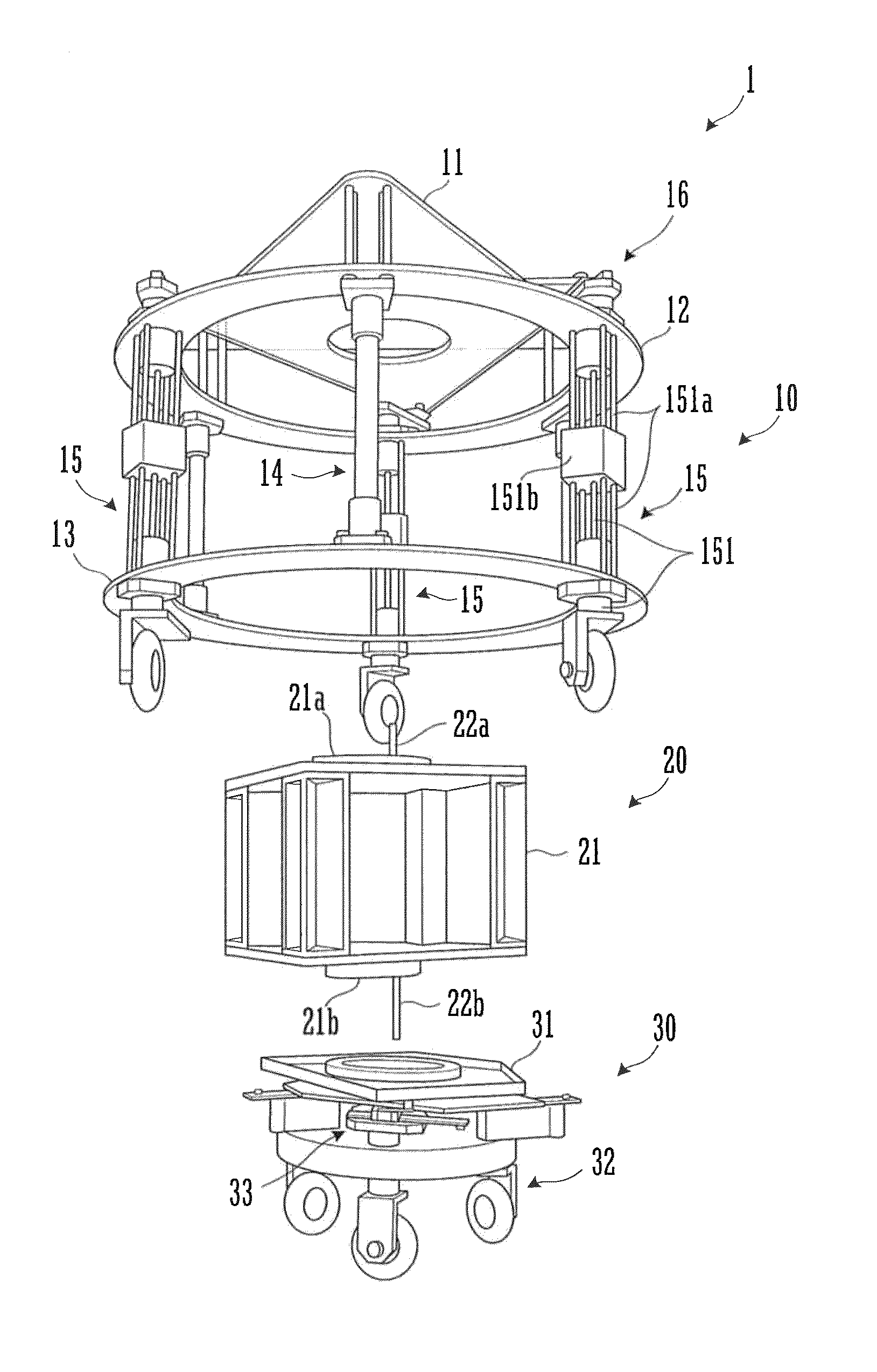
[0045]Firstly, the basic configuration and its relating forms of a trochoid drive system of the present invention are described below. A trochoid drive system includes an action part that turns around a driving shaft; and a steering part that co-rotates with the action part and is relatively movable in two-dimensional directions on a turning plane. The action part includes a plurality of action members that are uniformly disposed at positions from the driving shaft by a predetermined radius and along a circumferential direction, each action member being provided rotatably at a corresponding steering shaft parallel to the driving shaft, and the steering part includes a link system that rotates each action member around the corresponding steering shaft. The link system includes: a guide body having a predetermined length in a length direction and attached to the steering shaft so that the length direction is in a radial direction of the steering shaft; and a moving body provided for e...


PUM


Abstract

A trochoid propulsion system includes wheels provided at three points of the outer edge of an outer wheel part that turns around a driving shaft; and a steering link part that co-rotates with the action part and is movable horizontally on a turning plane. The steering link part includes a liner slider including a guide member attached to a vertical steering shaft that rotates each wheel so that the length direction is in a radial direction of the steering shaft and a moving member that slides on the guide member. In a state where a center of rotation of the steering link part coincides with the driving shaft of the outer wheel part, a rotating shaft provided corresponding to the steering shaft is attached rotatably to the corresponding moving member at a position separated from the steering shaft by a predetermined distance.

Description

TECHNICAL FIELD[0001]The present invention relates to a trochoid drive system that drives an action part physically relating to the outside in a trajectory along a trochoid curve.BACKGROUND OF THE INVENTION[0002]Patent Literature 1 proposes a technique of using a trochoid propulsion system to move a legless-chair type vehicle omni-directionally on the floor, the vehicle including eight casters exposed downward and a pair of antislip rear wheels. This system includes the eight casters uniformly arranged around a pivot of a turning cylinder and allows a tie rod engaged with each of the eight casters to steer the rotating directions of the eight casters. More specifically, the tie rod corresponding to each caster is configured to be integrally rotatable with a central base, and in the state where the central base and the pivot coincide with each other in their positions, the cylinder simply turns and the vehicle is in a stopped state. On the other hand, when a steering operation is per...

Claims


Application Information

Patent Timeline
Patent Type & Authority Patents(United States)
IPC IPC(8): B62D1/28
CPCB62D3/02B63H1/10B64C11/00B64D35/00Y10T74/20012
Inventor MAEDA, TAROANDO, HIDEYUKI
Owner OSAKA UNIV
Why Eureka
Try Eureka