Water-saving valve

a technology of water-saving valves and valve bodies, which is applied in the direction of mechanical equipment, functional valve types, transportation and packaging, etc., can solve the problems of discordant noise, and waste of water in the movement, so as to reduce the negative pressure wave generated, noise and damage to the water pipe are also prevented.

Active Publication Date: 2014-06-24
NEOPERL
View PDF12 Cites 14 Cited by
  • Summary
  • Abstract
  • Description
  • Claims
  • Application Information

AI Technical Summary

Benefits of technology

[0011]A water-saving valve assembly has a base, a control valve device and a buffer device. The control valve device is mounted in the base. The water-saving valve assembly is mounted on an exit of a water pipe. Users can control the flowing out or stopping of water in the water pipe via the control valve device. The buffer device provides a gradual effect of switching off and can effectively reduce positive and negative pressure waves generated in the water pipe. Noises and damage to the water pipe are also prevented.

Problems solved by technology

However, a user has to raise his / her hand to switch off the valve assembly located at the top of the tap after washing And this movement wastes water.
Users may have to try many times to make the hands properly placed in the sensing zone and this is inconvenient.
However, water still tends to flow toward the exit when the water-saving valve assembly is switched off.
This condition causes discordant noises and damage to the water pipe.
The operation is not smooth and inconvenient.

Method used


Image

  • Water-saving valve
  • Water-saving valve
  • Water-saving valve

Examples


Embodiment Construction

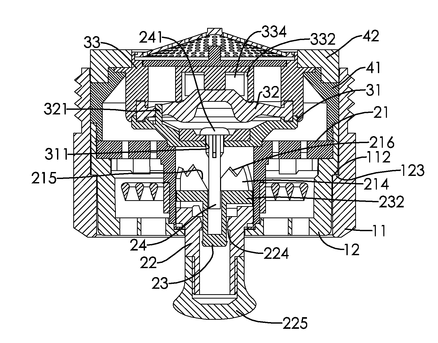
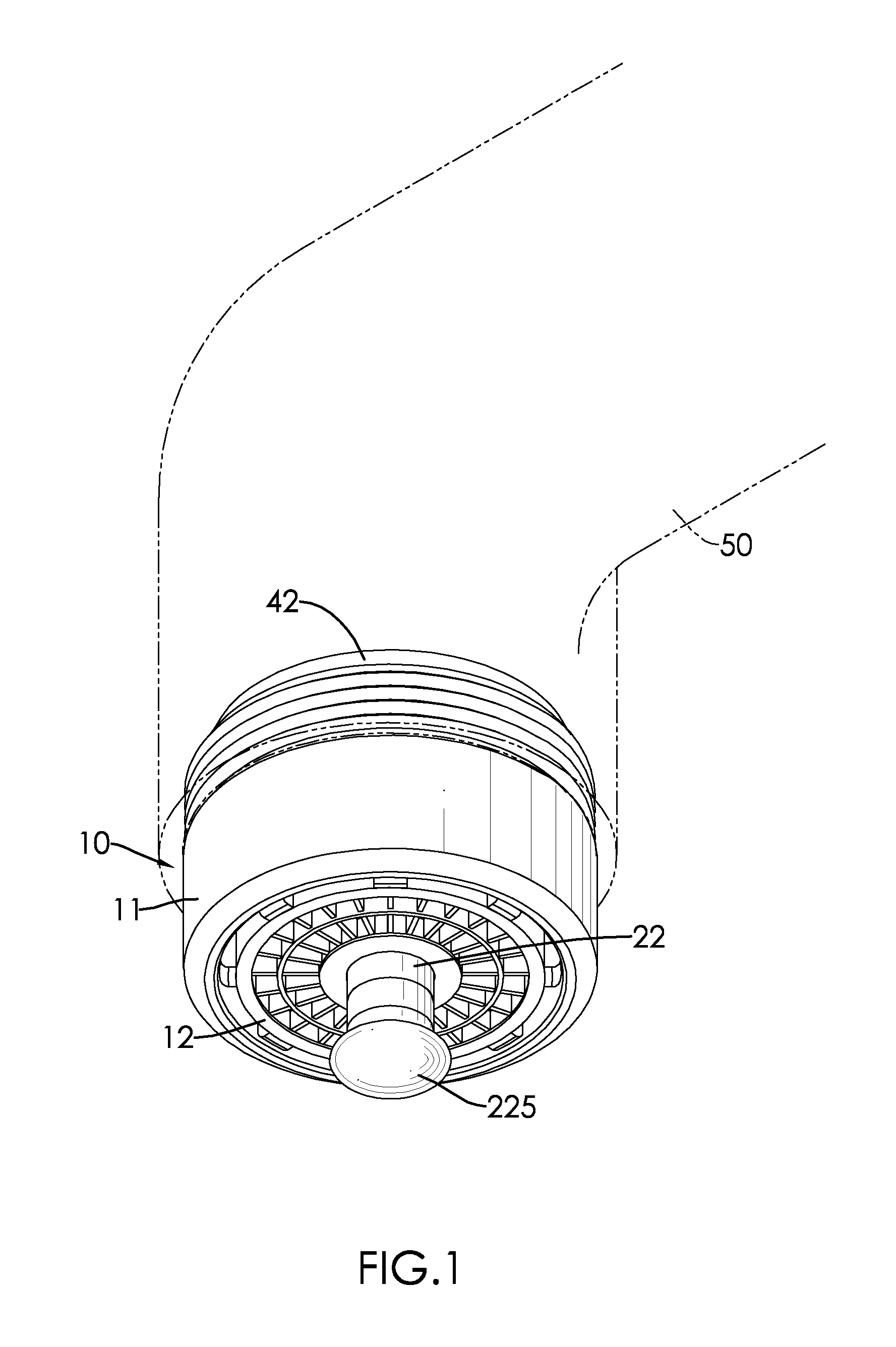
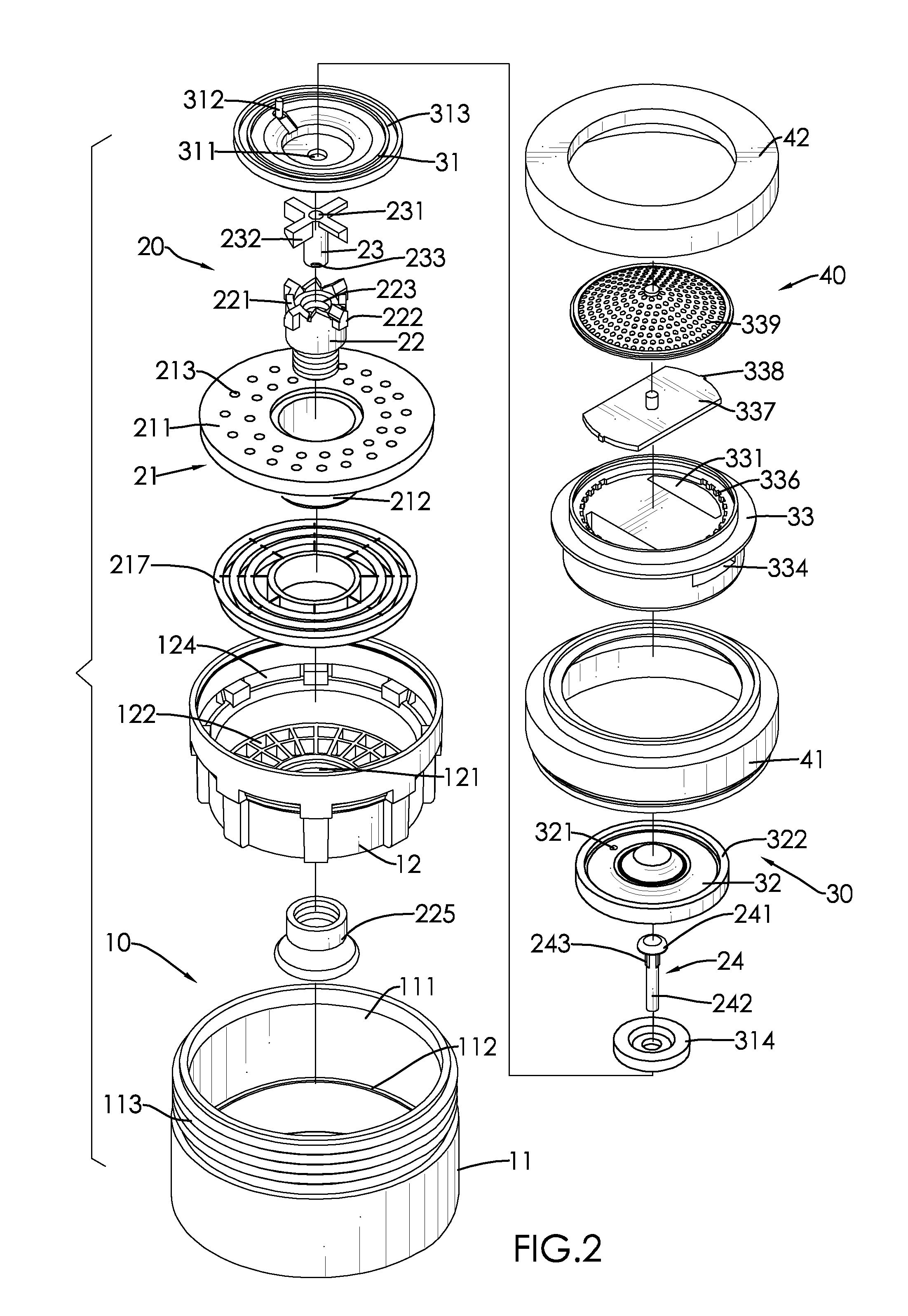
[0020]With reference to FIGS. 1 to 3, a water-saving valve assembly in accordance with the present invention comprises a base 10, a control valve device 20, a buffer device 30 and a cover device 40.

[0021]The base 10 has a tube 11 and a foaming sprout 12. An encompassing hole 111 of the tube 11 is located at a central section of the tube 11 and is step-shaped. A diameter of a top end of the encompassing hole 111 is larger than that of a bottom end of the encompassing hole 111. A step surface 112 is formed between the diameter of the top end of the encompassing hole 111 and the diameter of the bottom end of the encompassing hole 111. An exterior threaded surface 113 is formed on an outer surface of the tube 11.

[0022]The foaming sprout 12 is mounted in the encompassing hole 111 of the tube 11 and has a through hole 121. The through hole 121 is formed through a central section of a bottom of the foaming sprout 12. Multiple outlets 122 are formed around the through hole 121 and are arran...


PUM


Abstract

A water-saving valve assembly has a base, a control valve device and a buffer device. The control valve device is mounted in the base. The water-saving valve assembly is mounted on an exit of a water pipe. Users can control the flowing out or stopping of water in the water pipe via the control valve device. The buffer device provides a gradual effect of switching off and can effectively reduce positive and negative pressure waves generated in the water pipe. Noises and damage to the water pipe are also prevented.

Description

[0001]The present invention is a national stage of international application No. PCT / CN2010 / 000209, filed on Feb. 12, 2010.BACKGROUND OF THE INVENTION[0002]1. Field of the Invention[0003]The present invention relates to a water-saving valve assembly, and more particularly to a water-saving valve assembly having a buffer function.[0004]2. Description of Related Art[0005]A conventional valve assembly is mounted on a top of a tap and has a simple structure. However, a user has to raise his / her hand to switch off the valve assembly located at the top of the tap after washing And this movement wastes water.[0006]In order to resolve the problem of wasting water, an infrared-sensor valve assembly is created. When being washed, hands of a user are placed at a sensing zone to activate the infrared-sensor valve assembly by means of infrared light. After washing, the infrared-sensor valve assembly is automatically switched off because the hands are removed. Therefore, a water-saving effect is ...

Claims


Application Information

Patent Timeline
Patent Type & Authority Patents(United States)
IPC IPC(8): B05B7/06B05B1/16F16K21/00B05B1/30A62C31/00
CPCE03C2001/0414B05B1/1636B05B1/3026F16K47/02E03C1/08B05B1/1609E03C1/0412Y10T137/9464F16K47/01F16K1/36
Inventor KAO, CHIH-HUNGKAO, YU-YUEH
Owner NEOPERL
Why Eureka
Try Eureka