Device for collecting liquid samples for a vat

a technology for liquid samples and vats, which is applied in the field of devices for collecting liquid samples from a, can solve the problems of incomplete return to the vat, affecting quality, and limiting quality, so as to facilitate the proper direction of compressed air, facilitate manipulation, and reduce resistance

Inactive Publication Date: 2014-06-24
COMMISSARIAT A LENERGIE ATOMIQUE ET AUX ENERGIES ALTERNATIVES
View PDF14 Cites 2 Cited by
  • Summary
  • Abstract
  • Description
  • Claims
  • Application Information

AI Technical Summary

Benefits of technology

[0006]This arrangement makes it possible to use compressed air to produce the suction by releasing pressure in the nozzle, then, as soon as the valve is closed, to clean the pipe by reversing its circulation toward the vat, which rejects the droplets of the liquid that are still contained therein.
[0007]The pipe advantageously comprises a small reservoir and the sampling jug holder is able to be connected to the small reservoir by the intermediary of a self-sealing quick-coupling in two portions, a first of said portions belonging to the small reservoir and a second of said portions comprising a needle which penetrates inside the small reservoi

Problems solved by technology

A disadvantage with these devices is that the return to the vat is not complete and that droplets of liquid remain on the pipe, and then crystallise: this can be considered as a pollutant, and limits the quality of the following measurements by mixing wi

Method used


Image

  • Device for collecting liquid samples for a vat
  • Device for collecting liquid samples for a vat
  • Device for collecting liquid samples for a vat

Examples


Embodiment Construction

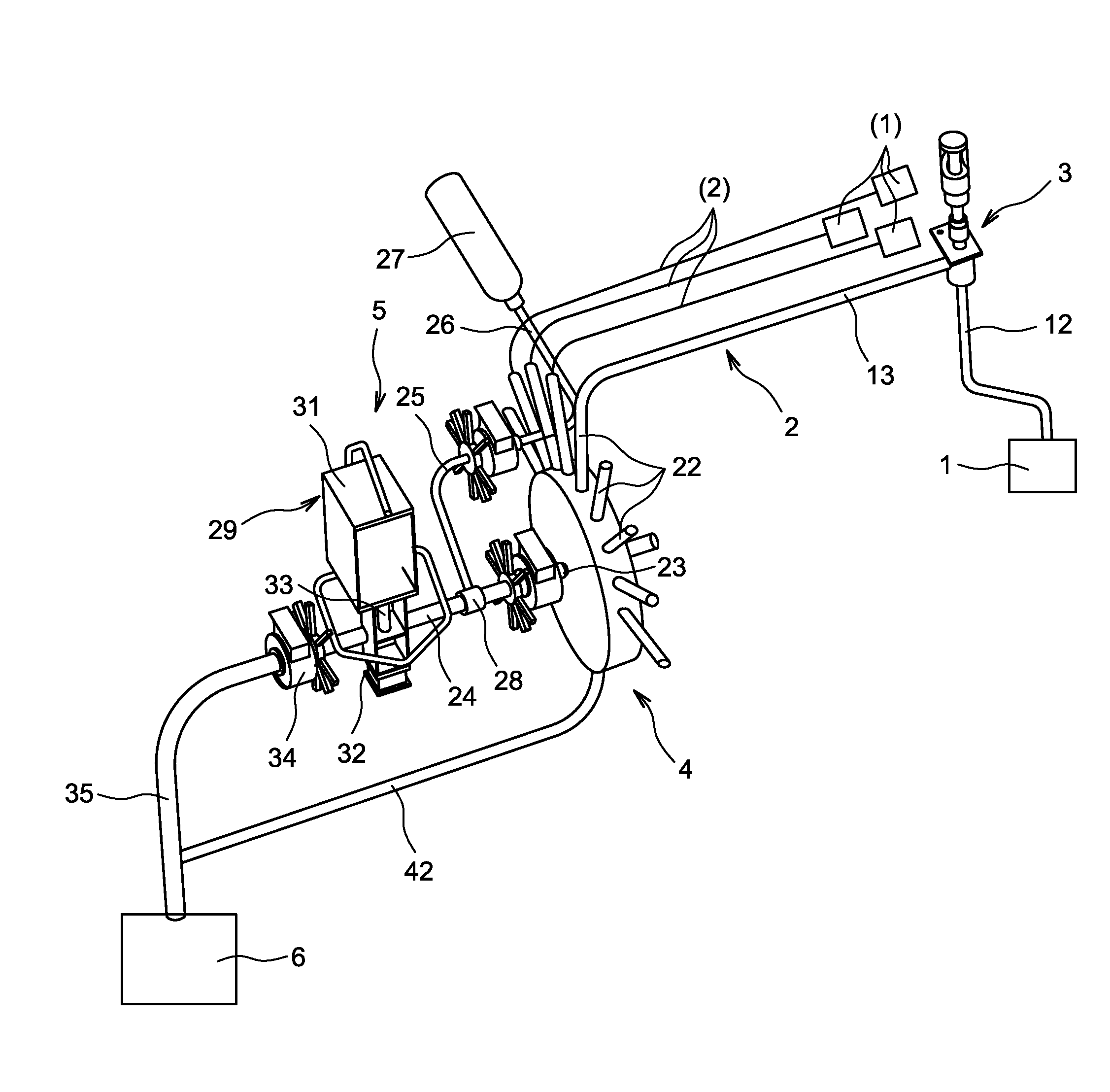
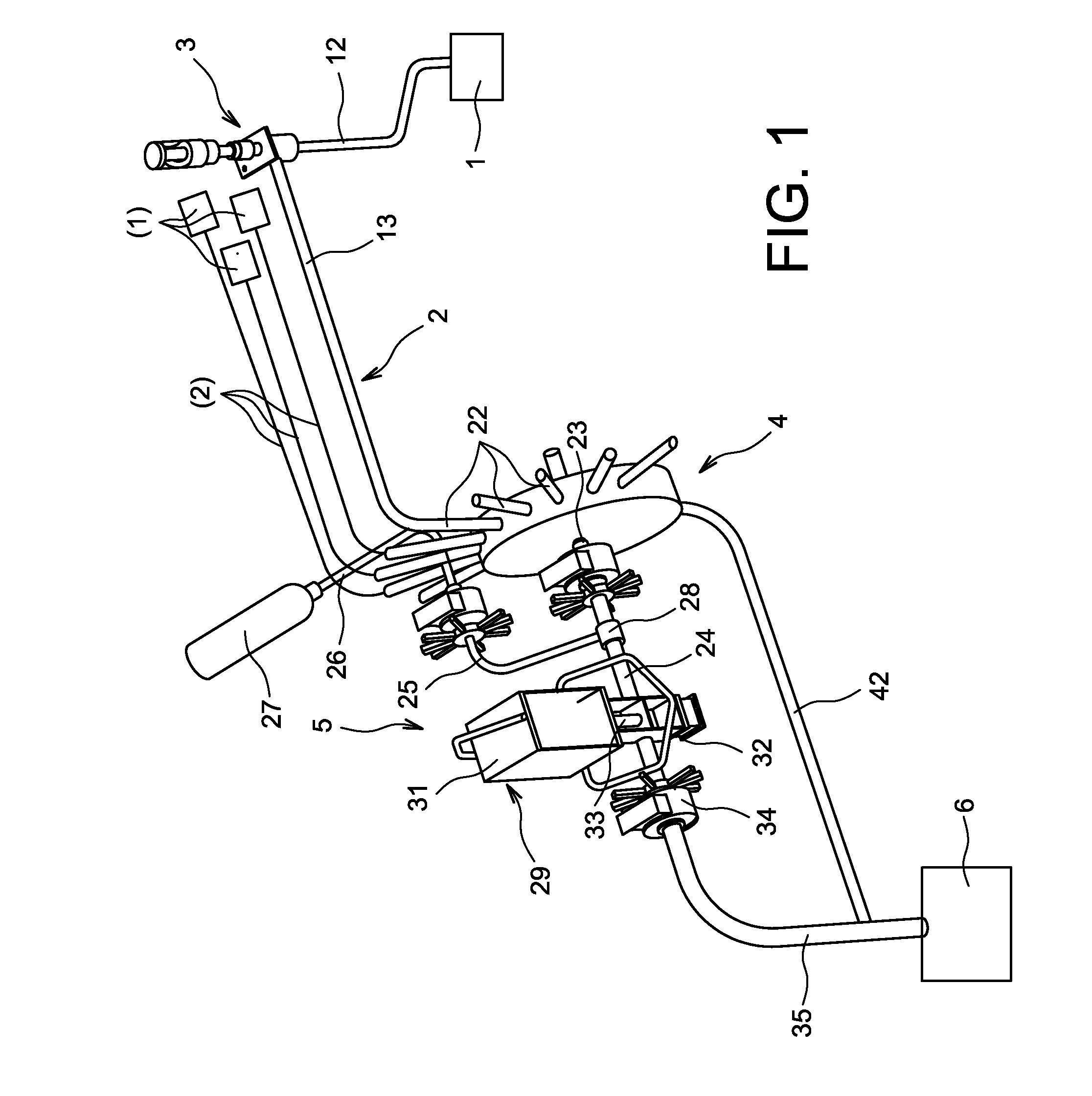
[0018]Reference shall first be made to FIG. 1. The liquid to be sampled is initially located in storage vats 1. Pipes 2 for sampling exit at the top of the vats 1, pass through a sampling installation 3, respective, are connected to a joint selector 4, then pass through a suction unit 5, and finish toward an outlet 6 which is a reservoir for collecting the excess sucked liquid. The main elements of the device shall now be described successively. The pipes 2 rise first from the vats 1, to the sampling installations 3, then fall little by little toward the outlet 6, opposite the vats 1 and therefore separate from them.

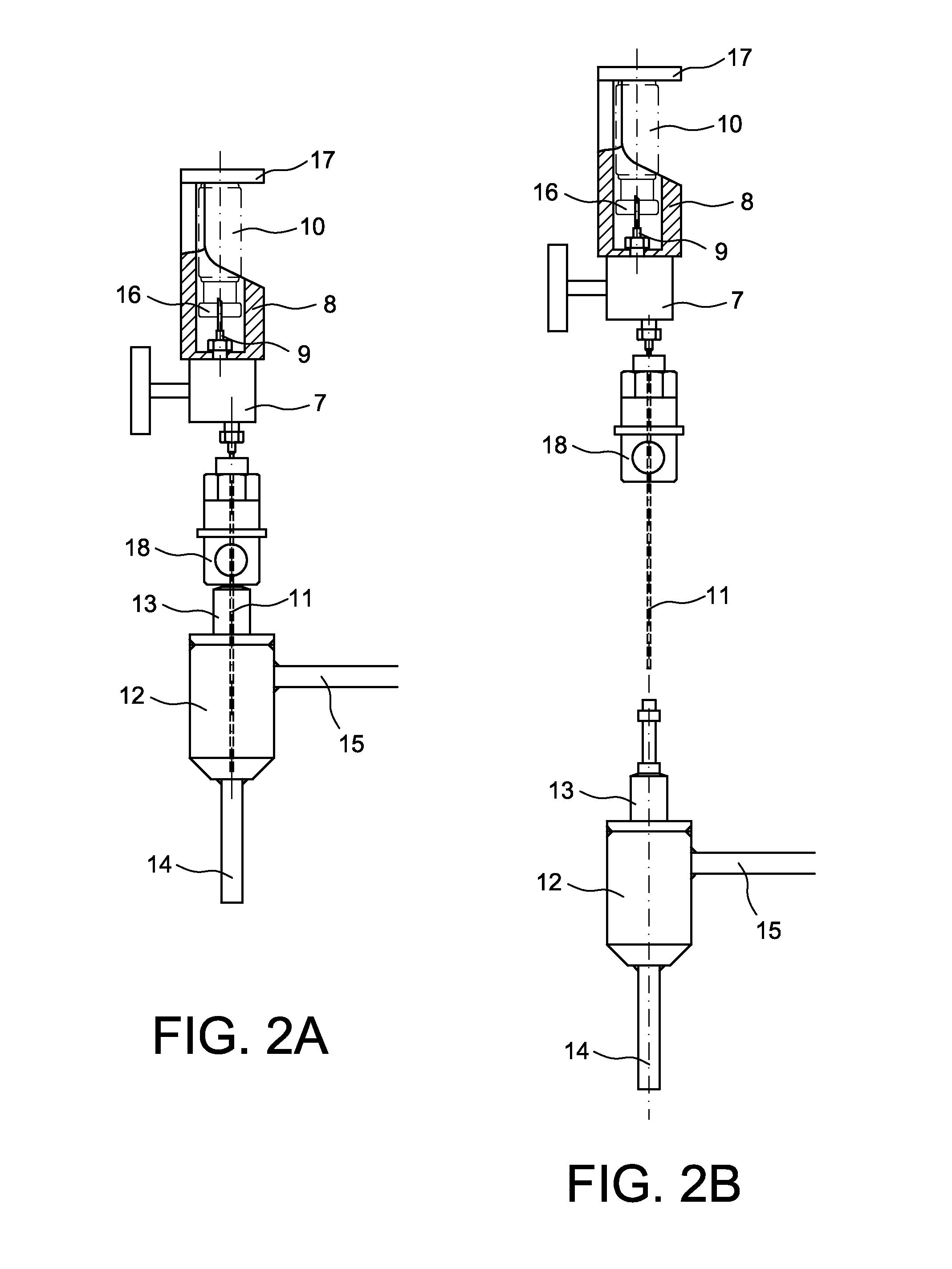
[0019]The sampling system 3 is shown in detail in FIG. 2. It first comprises a mobile portion constituted of a manual valve 7 of which the top is occupied by a cylindrical case 8 open at the top comprising an upper needle 9 whereon can be installed the jug 10 and a pivoting portion 17 making it possible to imprison the jug 10 in its housing, and the base via a needle 11 ...


PUM


Abstract

It comprises, in addition to a sampling system (3), at the outlet of a vat (1) containing the liquid to be sampled, a selector (4) that establishes switching on an array of similar vats (1), and especially a suction unit (5) that operates by releasing compressed air into a nozzle (28); the airflow direction is controlled by a valve (29) between a direction directed toward the outlet (6), causing the suction of the liquid from the vat (1), and an opposite direction when the valve (29) is closed, feeding the liquid back into the vat (1) and cleaning the pipe (2).

Description

FIELD OF THE INVENTION[0001]The invention relates to a device for collecting liquid samples from a vat, and even from a plurality of vats.BACKGROUND OF THE INVENTION[0002]Such devices are common in the nuclear industry in order to analyse certain liquids loaded with irradiating materials. The corresponding devices are generally placed in shielded units, and they are manipulated through the use of remote manipulators. The liquid to be analysed is first present in a vat. It undergoes a suction through a pipe exiting into the top of the vat, which carries it toward a sampling holder whereon a small container, generally called a jug, has been installed, and it partially fills this jug. The excess liquid is evacuated toward an outlet or returns to the vat by flowing through the pipe, which is inclined, as soon as the suction has stopped.[0003]A disadvantage with these devices is that the return to the vat is not complete and that droplets of liquid remain on the pipe, and then crystallis...

Claims


Application Information

Patent Timeline
IPC IPC(8): B01L3/02G01N1/00G01N1/10G01N1/14G01N33/00
CPCG01N1/14G01N2001/1037G01N2001/1463G01N2033/0093
Inventor BRENNEIS, CHRISTOPHELAGRAVE, HERVEMAMERT, JACQUES
Owner COMMISSARIAT A LENERGIE ATOMIQUE ET AUX ENERGIES ALTERNATIVES
Why Eureka
Try Eureka