Drive through air compressor with cone clutch

a cone clutch and air compressor technology, applied in the direction of interengaging clutches, positive displacement liquid engines, piston pumps, etc., can solve the problems of increasing the complexity and cost of the system, the device of plantan patent and christmas application suffers from significant disadvantages, and the rotational power goes to waste, etc., to achieve simple and inexpensive repair, installation and maintenance, simple and inexpensive coupling, and simple and inexpensive manufacturing

Active Publication Date: 2014-07-01
HALDEX BRAKE
View PDF24 Cites 4 Cited by
  • Summary
  • Abstract
  • Description
  • Claims
  • Application Information

AI Technical Summary

Benefits of technology

[0013]It is another object of the present invention to provide a crankshaft assembly that is simple and inexpensive to repair, install, and maintain.
[0014]It is yet another object of the present invention to provide a crankshaft assembly that has a simple means of coupling to one or more vehicle accessories.
[0015]It is still another object of the present invention to provide a crankshaft assembly that is simple and inexpensive to manufacture.
[0024]According to a third embodiment of the present invention, an assembly that selectively provides rotational power to a first vehicle accessory while continuously providing rotational power to a second vehicle accessory is provided, which includes a hollow cylindrical crankshaft coupled to the first vehicle accessory, a cylindrical driveshaft coupled to the second vehicle accessory, a source of rotational power coupled to the driveshaft and providing continuous rotational power to the second vehicle accessory, and a cone clutch assembly connected to the first vehicle accessory. The driveshaft is disposed coaxially within the hollow crankshaft. The cone clutch assembly includes a male clutch member having a conical shape with an external conical surface. The male clutch member is coupled to the driveshaft by involute splines to permit movement of the male clutch member relative to the driveshaft along the axis of the driveshaft while prohibiting radial movement of the male clutch member relative to the driveshaft. The cone clutch assembly also includes a female clutch member having a conical cup shaped portion with an internal conical surface and an output shaft portion, wherein the conical cup shaped portion and the output shaft portion are formed as a single piece. The output shaft portion is coupled to the crankshaft by involute splines to prohibit movement of the female clutch member relative to the crankshaft. The cone clutch assembly has an engaged state in which the male clutch member is positioned along the axis of the driveshaft such that the external conical surface comes into substantially flush contact with the internal conical surface of the female clutch member so that rotational power is transmitted from the driveshaft and male clutch member to the female clutch member and crankshaft, thereby providing rotational power to the first vehicle accessory.

Problems solved by technology

This rotational power goes to waste whenever the clutch is disengaged.
The devices of the Plantan patent and the Christmas application suffer from significant disadvantages.
First, their use of multi-plate clutches increases the complexity and cost of the system while decreasing the reliability, ease of installation, and ease of maintenance of the system.
A further disadvantage of devices such as those disclosed by Plantan and Christmas is that disassembly of the device for maintenance or repair of the multi-plate clutch is burdensome and time-consuming due to the complexity in the way in which the clutch is mated to the vehicle accessory.
This disadvantage exacerbates the problems relating to the complexity of the clutch itself.
However, problems still remain in the art relating to the difficulty in attaching and integrating the clutch system to the vehicle accessories.
In the device disclosed by the Carpenter et al. application, access to the clutch for maintenance or repair purposes would also be difficult.
If an accessory were to be driven by the driveshaft in addition to the air compressor on the input end of the driveshaft as disclosed, this would impede access to the clutch.
The Plantan patent and the Christmas application suffer from the additional disadvantage that their clutch components and first vehicle accessory components are intermingled.
The designs of the prior art cost valuable time whenever repair, maintenance, or replacement is needed.
This is due not only of the increased complexity of the multi-plate clutch design, but also the lack of a simple interface between the clutch system and the vehicle accessory.

Method used


Image

  • Drive through air compressor with cone clutch
  • Drive through air compressor with cone clutch
  • Drive through air compressor with cone clutch

Examples


Embodiment Construction

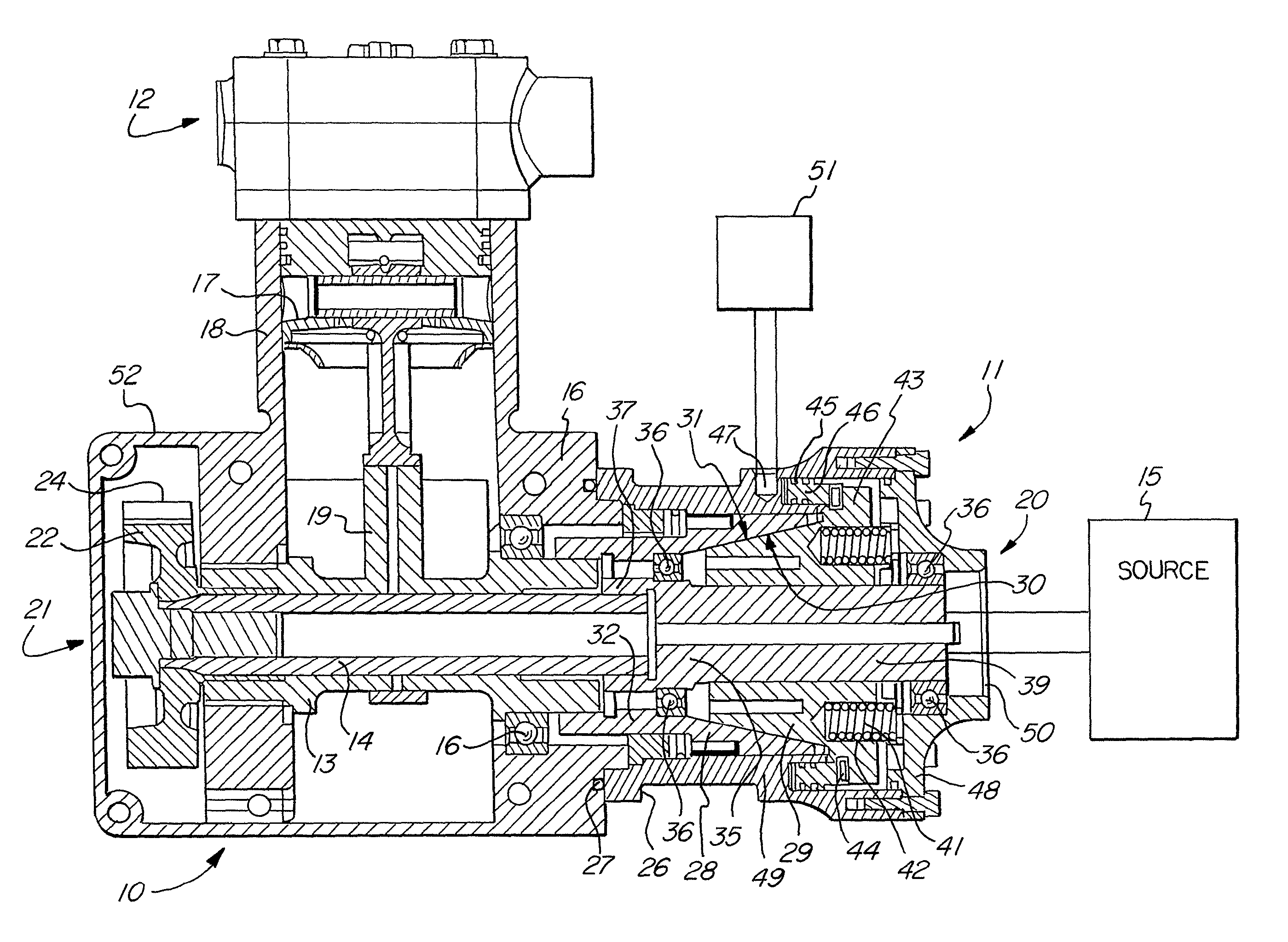
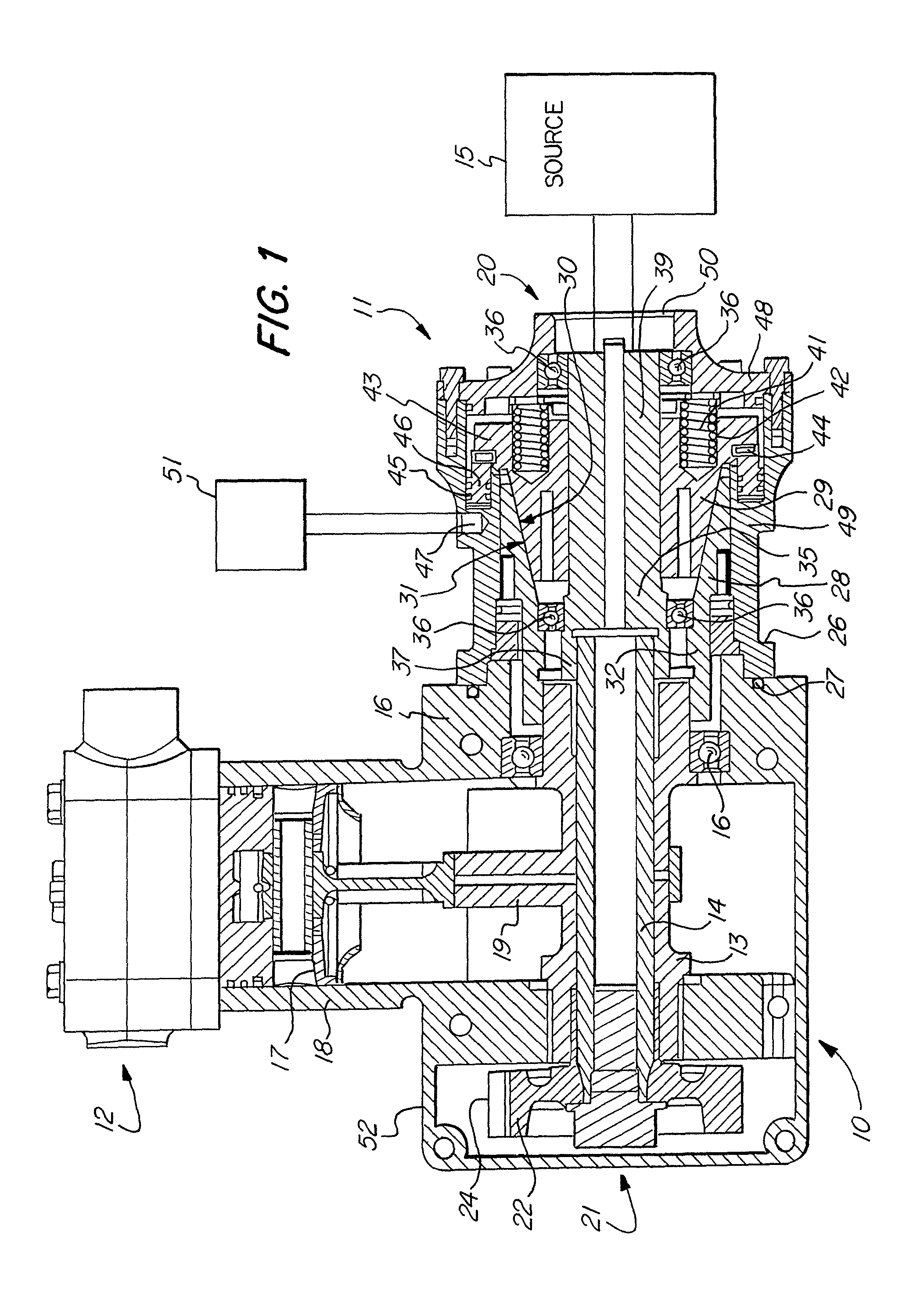
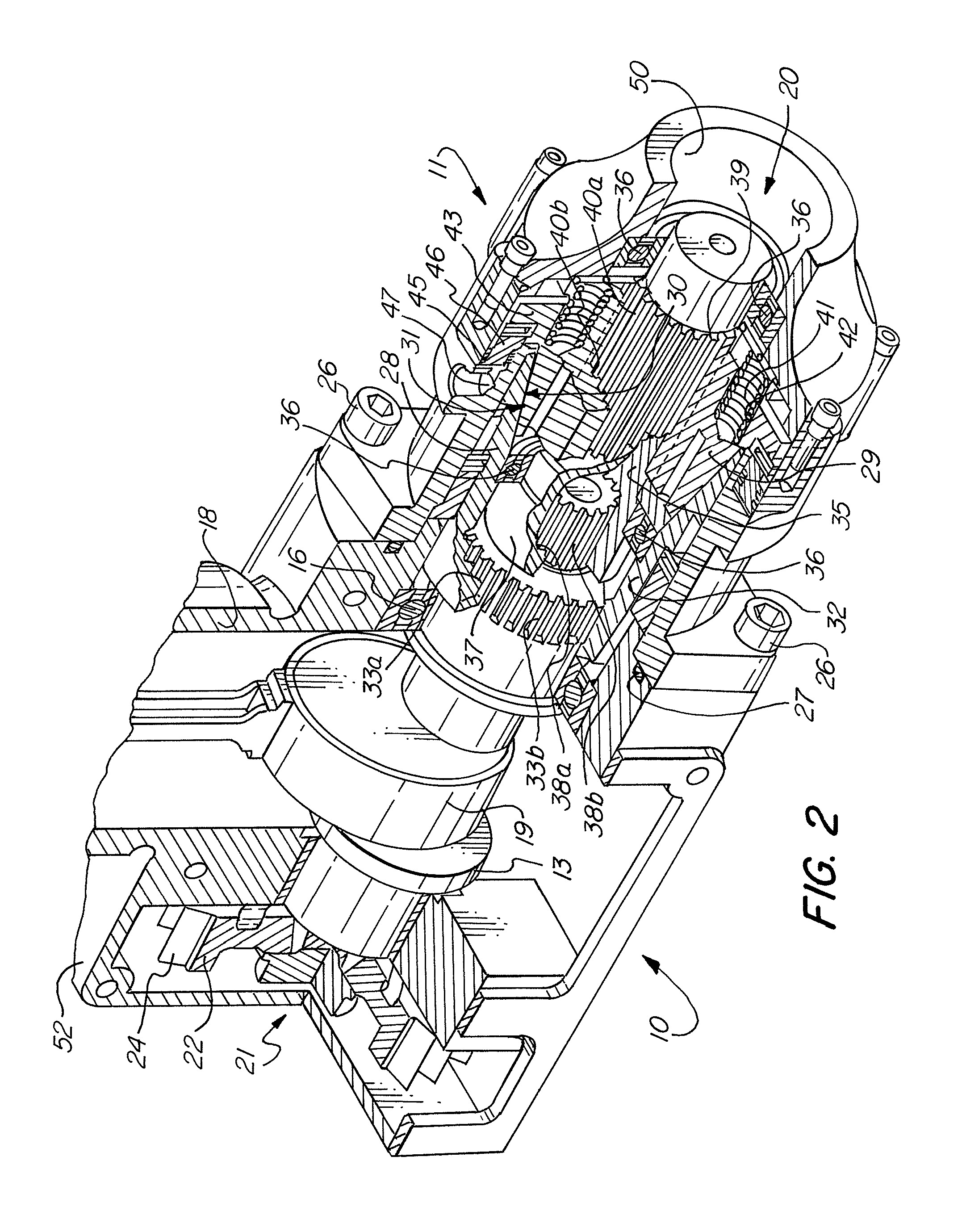
[0033]An embodiment of the present invention will now be described with reference to the attached FIGS. 1-3, wherein like numbers refer to like elements. FIG. 1 shows, in a longitudinal cross-section view, a crankshaft assembly 10 having a proximal side 20 and a distal side 21. FIG. 2 shows the crankshaft assembly 10 in an isometric cross-section view, which more clearly shows certain of the elements of the crankshaft assembly 10.

[0034]The crankshaft assembly 10 includes a first vehicle accessory, in this case an air compressor 12, a cone clutch 11, a crankshaft 13, a driveshaft 14, and a source of rotational power 15.

[0035]The crankshaft 13 has a cylindrical bore along its longitudinal axis such that it is substantially hollow. The driveshaft 14 is disposed within the cylindrical bore of the crankshaft 13 and protrudes from both the proximal end and the distal end of the crankshaft 13. The crankshaft 13 and the driveshaft 14 are designed so that each can rotate independently of one...


PUM


Abstract

A drive through crankshaft assembly which selectively provides rotational power to a vehicle accessory while continuously providing rotational power to a second vehicle accessory. Rotational power is selectively provided using a cone clutch assembly that is modular. The cone clutch assembly provides power to the first vehicle accessory when it is in an engaged state. The first vehicle accessory is turned off by putting the cone clutch assembly into a disengaged state using a clutch control system.

Description

FIELD OF THE INVENTION[0001]The present invention relates to a crankshaft assembly for selectively providing rotational power to at least one vehicle accessory while continuously supplying rotational power to at least one other vehicle accessory. In particular, this invention relates to a crankshaft assembly including a cone clutch device and a drive through air compressor.BACKGROUND OF THE INVENTION[0002]It is well-known in the art to utilize a clutch to selectively provide rotational power to a vehicle accessory such as an air compressor or other reciprocating device. U.S. Pat. Nos. 4,648,805, 4,632,639, and 4,561,827 to Beaumont each relate to an air compressor having a piston driven by a crankshaft. The crankshaft is supplied with rotational power by a multi-plate clutch when the clutch is engaged. The multiplate clutch has a driving portion and a driven portion. The driving portion of the clutch is provided with rotational power by a driveshaft. The piston of the air compressor...

Claims


Application Information

Patent Timeline
Patent Type & Authority Patents(United States)
IPC IPC(8): F02B63/00
CPCF04B27/0895B60T17/02F04B35/002F16D25/082F04B35/00F04B53/00
Inventor FETTER, TRAVIS L.JENKINS, MICHAEL R.
Owner HALDEX BRAKE
Why Eureka
Try Eureka