Tension-based tension leg platform

a technology of tension leg and platform, which is applied in the direction of anchoring arrangement, vessel construction, construction, etc., can solve the problems of tlp tendon requirement to keep the vessel concept effective within the practical cost budget, dynamic system is susceptible to direct wave energy at resonance, and limited water depth limitation of tlp technology less than 5000

Inactive Publication Date: 2014-07-01
SRINIVASAN NAGAN
View PDF29 Cites 13 Cited by
  • Summary
  • Abstract
  • Description
  • Claims
  • Application Information

AI Technical Summary

Problems solved by technology

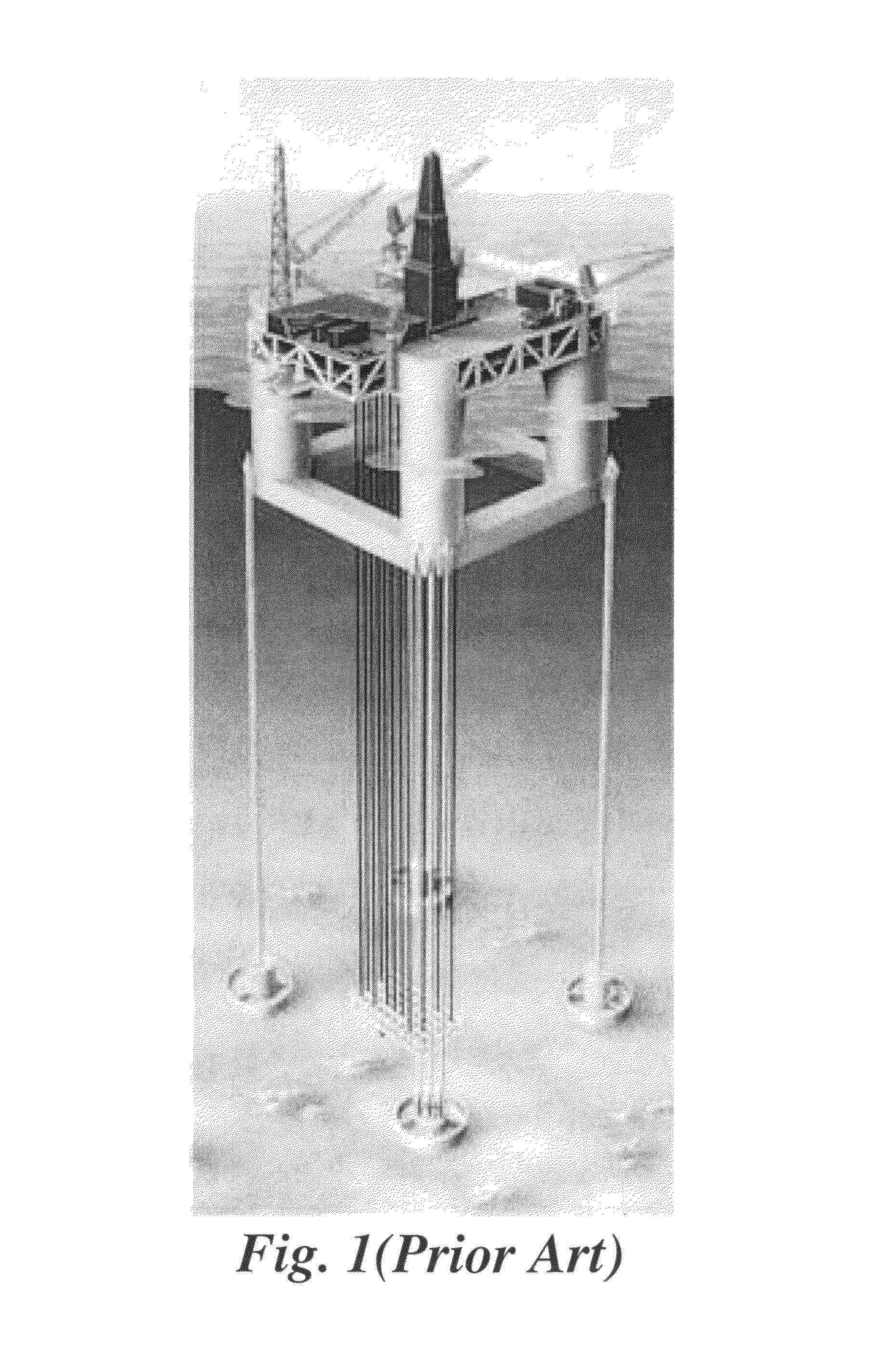
The water depth limitation of this TLP technology is less than 5000 ft for several technical reasons that are discussed hereinafter.
A TLP tendon requirement to keep the vessel concept effective within the practical cost budget is limited by the water depth.
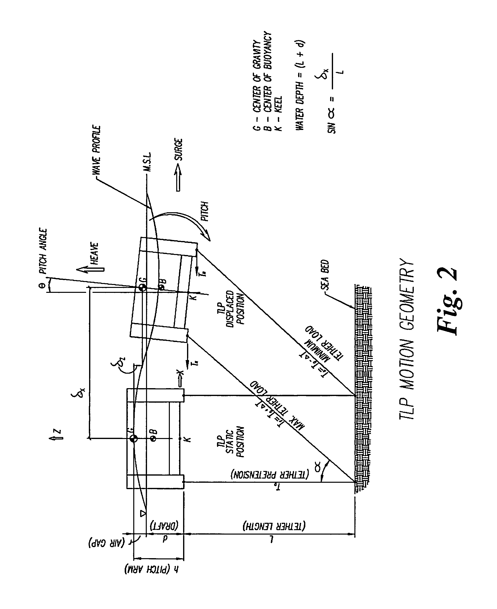
If the TLP's heave or pitch or roll periods become longer than 4-5 seconds, then the dynamic system is susceptible to direct wave energy at resonance.
That leads to motions and severe fatigue problems.
At water depths close to 5000 ft, the weight of the tendons becomes impractical.
The vessel size to always maintain the tendons in tension becomes uneconomically large.
However, they are not yet practical from the standpoint of cost.
As discussed above, one of the problems in extending TLP technology to ultra deepwater applications is that the TLP is sensitive to topside deck load because it loses its pretension capacity with respect to the topside weight for the given hull buoyancy.
Subsea well solutions although attractive in deepwater, requires well intervention when the well is not producing as expected and becomes expensive.
Many wells have been abandoned because the cost-effectiveness to fix them in the deep water with subsea wells.
As stated earlier, the TLP has a water depth limitation problem utilizing steel tendons.
Consequently, the installation of the vessel becomes difficult as the water depth increases beyond 5000 ft.
Water depth increases have more serious problems with the TLP applications.
The increased water depth increases the riser weight and thus increases the pretension.
This typically results in larger wall thickness for the risers.
This solution further increases the riser weight and the riser pretension requirements.
Thus the TLP vessel size becomes unusually large and the tendons design becomes challenging, and development of a new technology is required to use TLP in ultra deepwater fields.
Thus, designing a TLP for ultra deepwater has three basic problems: (1) Vessel Size, (2) Tendon Design, and (3) Riser Design.

Method used


Image

  • Tension-based tension leg platform
  • Tension-based tension leg platform
  • Tension-based tension leg platform

Examples


Embodiment Construction

Truss-Pontoon to TLP:

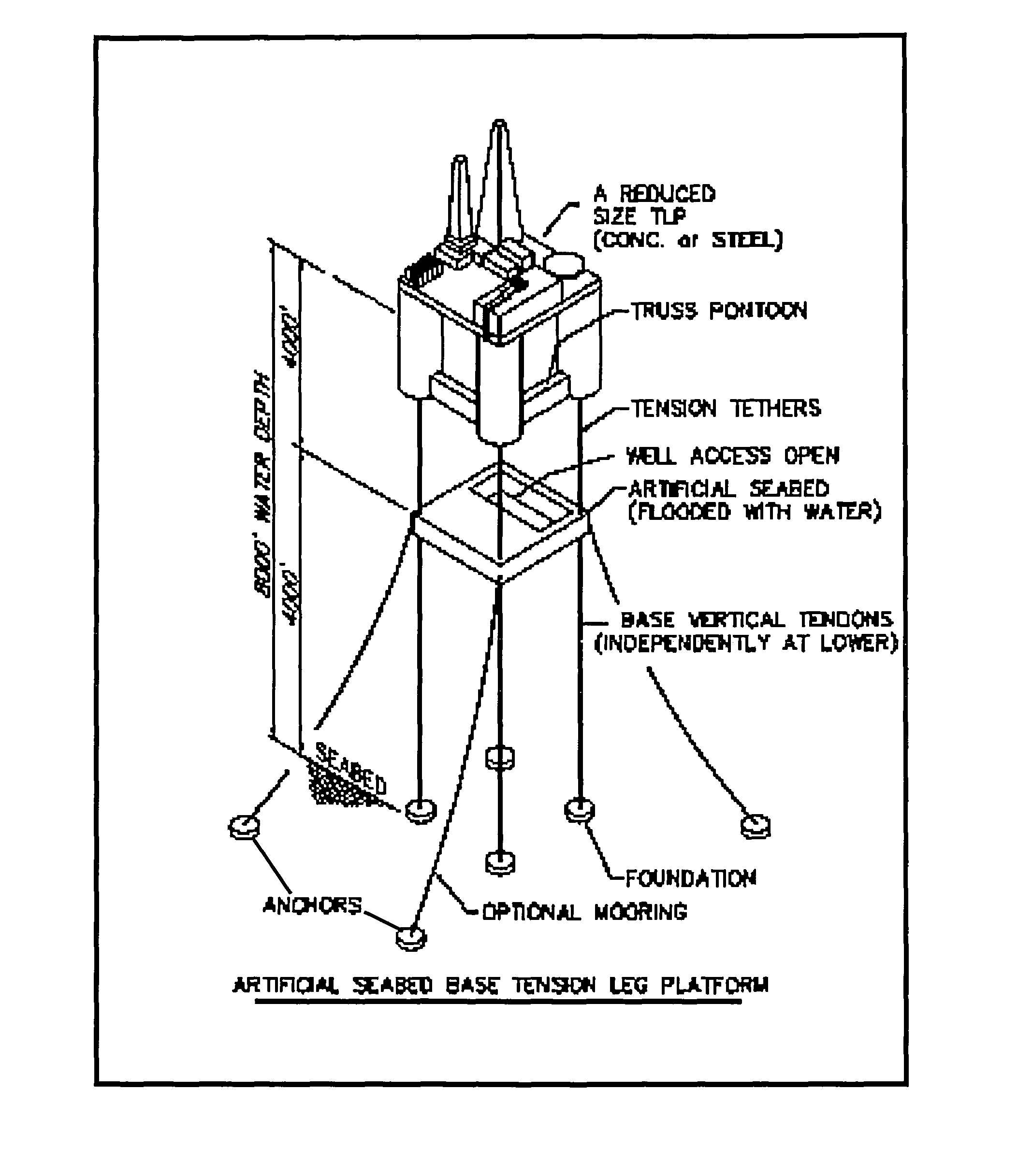
[0025]Referring now to FIG. 3, in order to achieve the above three goals, first a modified truss pontoon type hull is used in the present tension-based tension leg platform, for example, a truss pontoon type hull as shown and described in my U.S. Pat. No. 6,761,124, titled “Column-Stabilized Floating Structures with Truss-pontoons”, which is hereby incorporated by reference in its entirety. A semi-submersible platform having lateral trusses, a rectangular deck mount structure or a three-sided deck mount structure at the top of the columns open on one side to allow on-site float-over deck installation, and outwardly extending tendon support frame at the lower end of the columns, is shown and described in my pending U.S. patent application Ser. No. 12 / 378,888, titled “Dry Tree Semi-Submersible Platform For Harsh Environment And Ultra Deepwater Applications”, which is hereby incorporated by reference in its entirety.

[0026]Removing the pontoon from the conventional ...


PUM


Abstract

A tension-based tension leg platform (TBTLP) for use in ultra deepwater applications to support dry-tree oil and gas production utilizes a tension base or artificial seabed that simplifies tendon design at deepwater locations in harsh environment and has a truss pontoon structure that reduces vertical and horizontal wave loadings. The platform may include a riser support tower that makes production risers feasible in 8,000 ft water depths without riser pretension to the hull and reduces or eliminates vortex induced vibration problems.

Description

CROSS REFERENCE TO RELATED APPLICATION[0001]This application claims priority of U.S. Provisional Application Ser. No. 61 / 352,283 filed Jun. 7, 2010.BACKGROUND OF THE INVENTION[0002]1. Field of the Invention[0003]This invention relates generally to offshore floating structures, and, more particularly to a tension-based tension leg platform (TBTLP) for use in ultra deepwater to support dry-tree oil and gas production which utilizes a tension base or artificial seabed to simplify tendon design at deep water locations in harsh environment and a truss pontoon to reduce vertical and horizontal wave loadings.[0004]2. Background Art[0005]Oil and gas companies have used Tension Leg Platforms (TLP) for production in deepwater since 1980 until the alternate Truss-SPAR technology was developed and tested in the Gulf of Mexico. The TLP is an excellent and reliable technology because it has proven behavior in the harsh environment of deepwater. The industry takes no risk in using this technology ...

Claims


Application Information

Patent Timeline
Patent Type & Authority Patents(United States)
IPC IPC(8): E02D5/40B63B21/50E02D5/34
CPCB63B21/502
Inventor SRINIVASAN, NAGAN
Owner SRINIVASAN NAGAN
Why Eureka
Try Eureka