

Interphalangeal joint implant methods and apparatus
a technology of interphalangeal joint and implant device, which is applied in the field of methods and apparatus for correcting abnormal flexion of the joints of the human foot, can solve the problems of high non-union rate, failure or non-union, and insufficient comfort for individuals
- Summary
- Abstract
- Description
- Claims
- Application Information
AI Technical Summary
Benefits of technology
Problems solved by technology
Method used
Image

Examples
Embodiment Construction
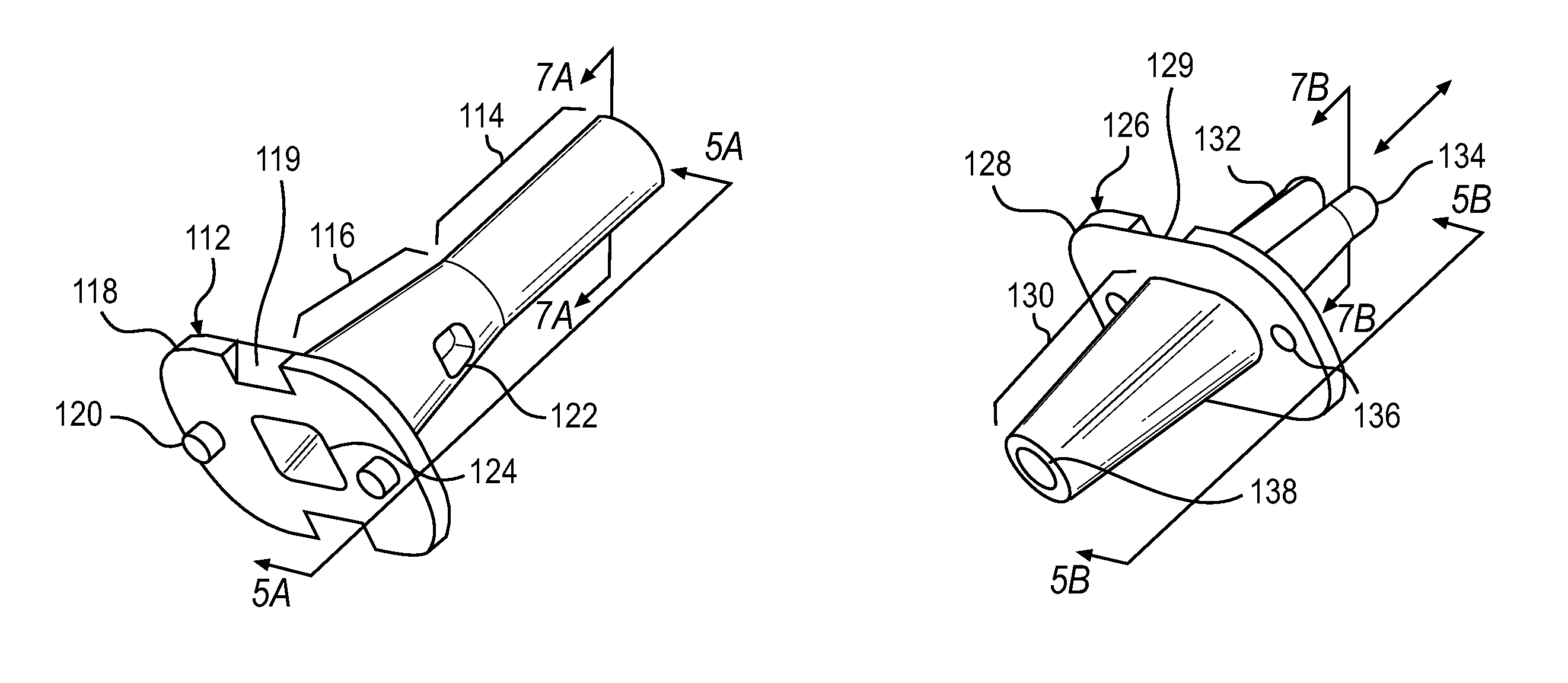
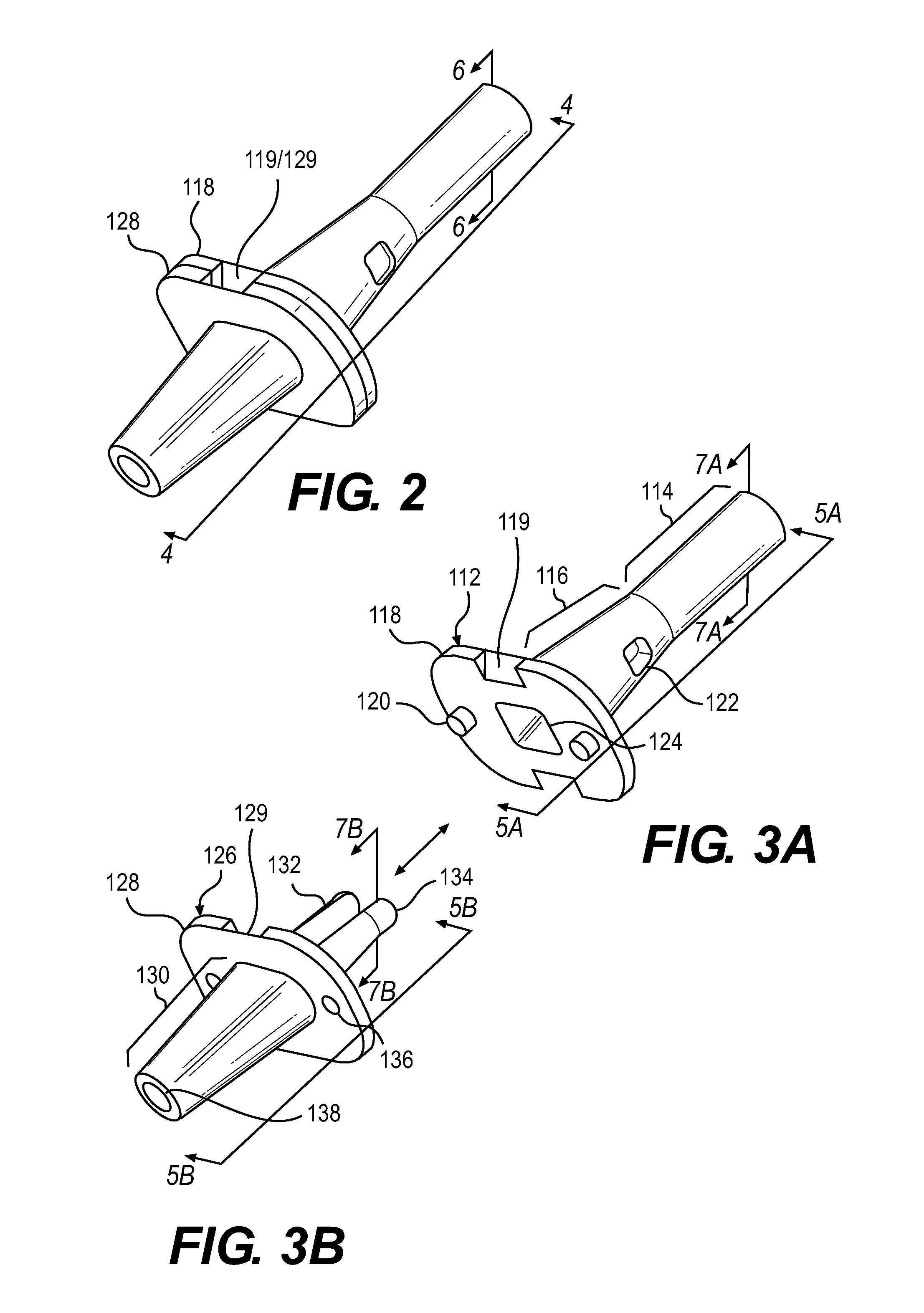
[0012]The subject disclosure includes advantages of bone fusion while simplifying the procedure and decreasing or eliminating incidences of non-union and non-alignment. A preferred embodiment comprises a two-component device including (1) a proximal phalanx component and (2) a middle phalanx component. The two components are handled separately during a surgical procedure. Each is inserted axially into a respective host bone. After insertion, the components are joined. The attached components are held together in various ways, for example a detent arm / aperture mechanism. As the components are brought together, the arms of one component slide into a central channel, or cannula, in the other component. The arms are spring loaded as they first encounter an inner surface of the cannula and then spring out when the arms encounter lateral apertures present further on along the cannula. Each component can be cannulated to allow for the passage of a wire, e.g. 0.045 inch kirschner wire (k-wi...
PUM
 Abstract
Description
Claims
Application Information