
Multi-field charged particle cancer therapy method and apparatus

a cancer therapy and charge particle technology, applied in the field of solid cancer treatment, can solve the problems of reduced ability to repair damaged dna, particularly vulnerable to attack on dna, and death of patients

Active Publication Date: 2014-07-01
GEORGIA TECH RES CORP
View PDF374 Cites 24 Cited by
  • Summary
  • Abstract
  • Description
  • Claims
  • Application Information

AI Technical Summary

Problems solved by technology

These particles damage the DNA of cells, ultimately causing their death.
Cancerous cells, because of their high rate of division and their reduced ability to repair damaged DNA, are particularly vulnerable to attack on their DNA.

Method used


Image

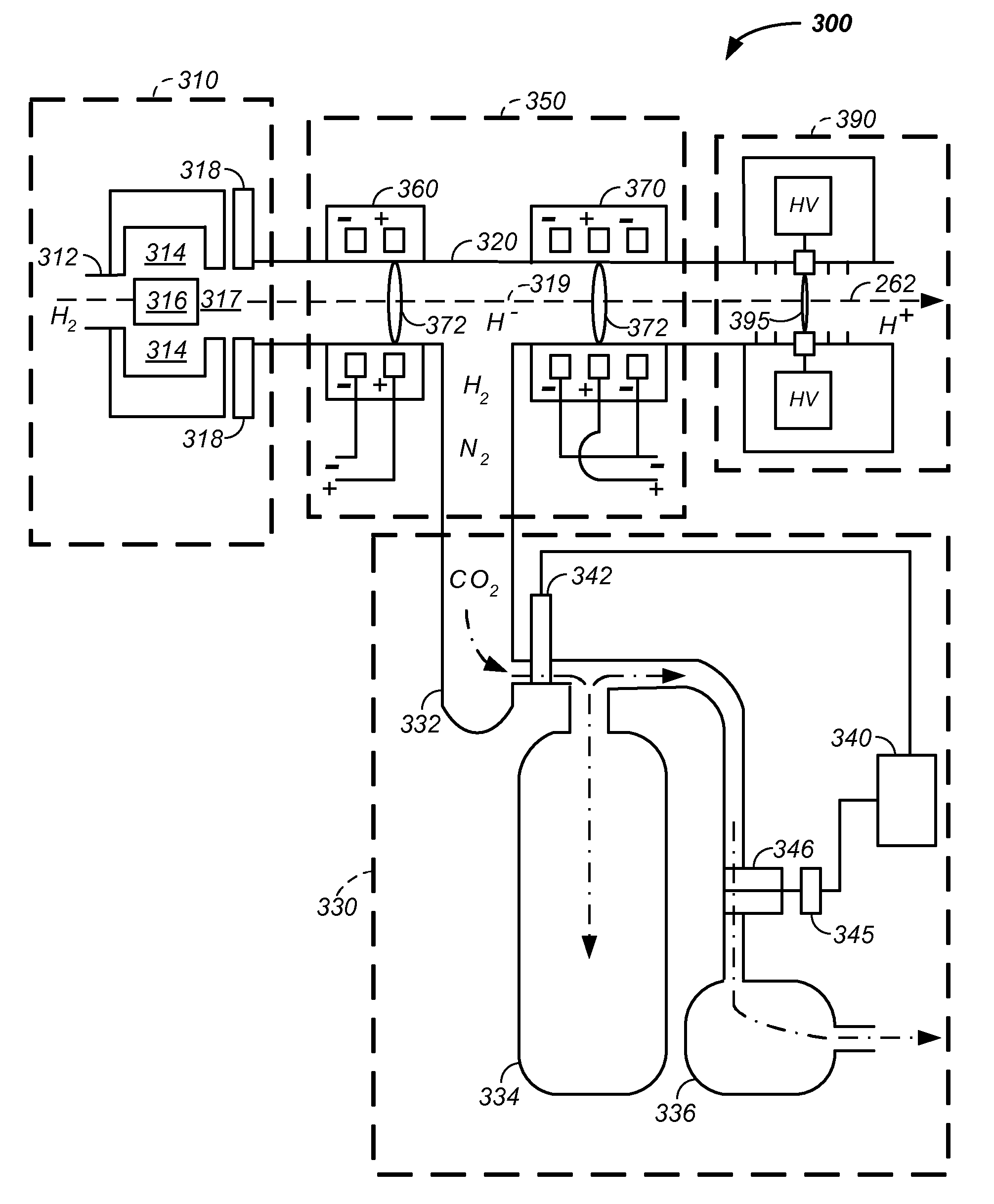
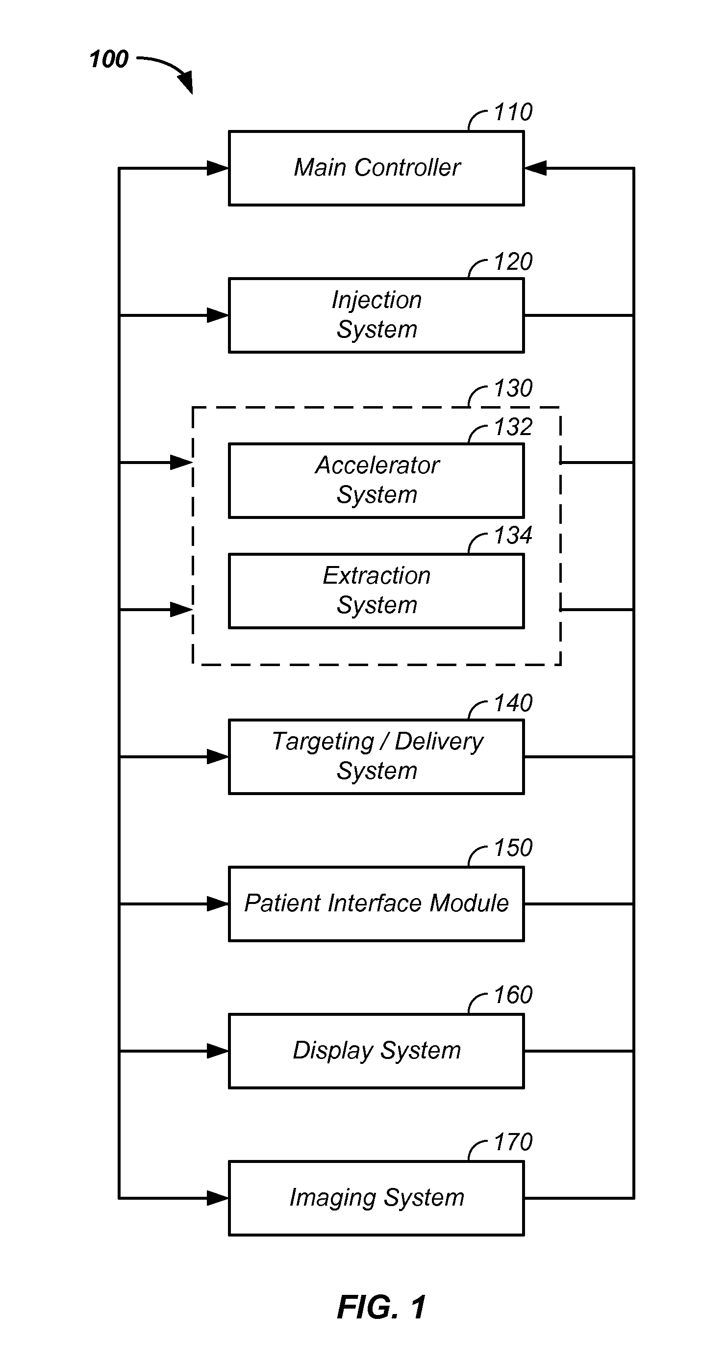
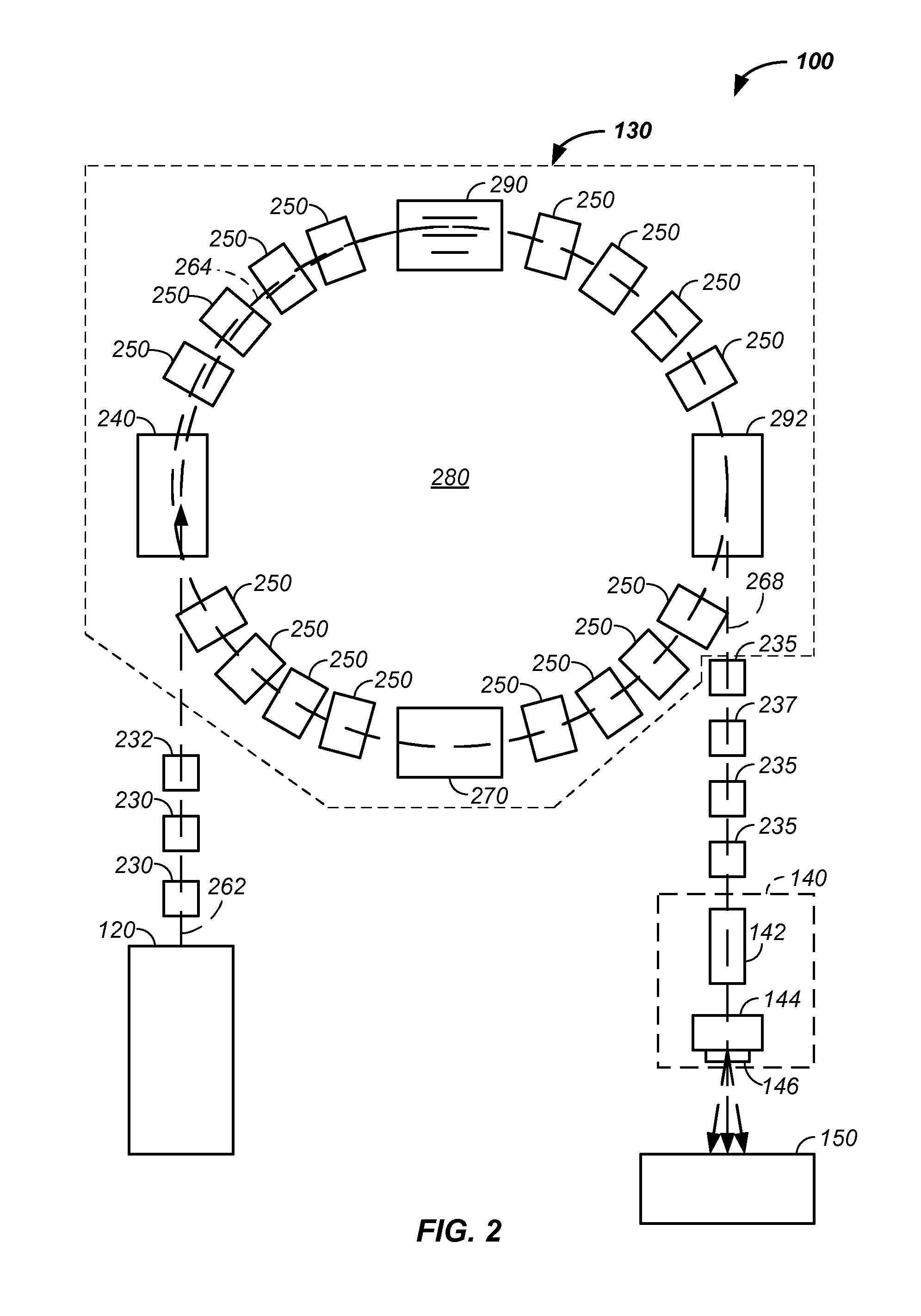
  • Multi-field charged particle cancer therapy method and apparatus
  • Multi-field charged particle cancer therapy method and apparatus
  • Multi-field charged particle cancer therapy method and apparatus

Examples


example iii

[0152]Referring again to FIG. 9, an example of a winding coil 930 that covers two turning magnets 510, 520 is provided. Optionally, a first winding coil 940 covers one magnets or a second winding coil 920 covers a plurality of magnets 510, 520. As described, supra, this system reduces space between turning section allowing more magnetic field to be applied per radian of turn. A first correction coil 910 is illustrated that is used to correct the magnetic field for the first turning magnet 510. A second correction coil 920 is illustrated that is used to correct the magnetic field for a winding coil 930 about two turning magnets. Individual correction coils for each turning magnet are preferred and individual correction coils yield the most precise and / or accurate magnetic field in each turning section. Particularly, the individual correction coil 910 is used to compensate for imperfections in the individual magnet of a given turning section. Hence, with a series of magnetic field sen...


PUM


Abstract

The invention comprises a multi-field charged particle irradiation method and apparatus. Radiation is delivered through an entry point into the tumor and Bragg peak energy is targeted to a distal or far side of the tumor from an ingress point. Delivering Bragg peak energy to the distal side of the tumor from the ingress point is repeated from multiple rotational directions. Preferably, beam intensity is proportional to radiation dose delivery efficiency. Preferably, the charged particle therapy is timed to patient respiration via control of charged particle beam injection, acceleration, extraction, and / or targeting methods and apparatus. Optionally, multi-axis control of the charged particle beam is used simultaneously with the multi-field irradiation. Combined, the system allows multi-field and multi-axis charged particle irradiation of tumors yielding precise and accurate irradiation dosages to a tumor with distribution of harmful irradiation energy about the tumor.

Description

CROSS REFERENCES TO RELATED APPLICATIONS[0001]This application claims the benefit of:[0002]U.S. provisional patent application No. 61 / 055,395 filed May 22, 2008;[0003]U.S. provisional patent application No. 61 / 137,574 filed Aug. 1, 2008;[0004]U.S. provisional patent application No. 61 / 192,245 filed Sep. 17, 2008;[0005]U.S. provisional patent application No. 61 / 055,409 filed May 22, 2008;[0006]U.S. provisional patent application No. 61 / 203,308 filed Dec. 22, 2008;[0007]U.S. provisional patent application No. 61 / 188,407 filed Aug. 11, 2008;[0008]U.S. provisional patent application No. 61 / 209,529 filed Mar. 9, 2009;[0009]U.S. provisional patent application No. 61 / 188,406 filed Aug. 11, 2008;[0010]U.S. provisional patent application No. 61 / 189,815 filed Aug. 25, 2008;[0011]U.S. provisional patent application No. 61 / 208,182 filed Feb. 23, 2009;[0012]U.S. provisional patent application No. 61 / 201,731 filed Dec. 15, 2008;[0013]U.S. provisional patent application No. 61 / 208,971 filed Mar. 3...

Claims


Application Information

Patent Timeline
Patent Type & Authority Patents(United States)
IPC IPC(8): A61N5/10
CPCG21K1/087H05H7/10G21K1/093H05H13/04A61N2005/1087H05H7/08H05H7/04G21K1/14
Inventor BALAKIN, VLADIMIR, YEGOROVICH
Owner GEORGIA TECH RES CORP
Learn More