Vehicle braking force control device

a technology of braking force and control device, which is applied in the direction of braking system, process and machine control, instruments, etc., can solve the problem of harder anti-lock brake control

Active Publication Date: 2014-07-01
BOSCH CORP
View PDF53 Cites 2 Cited by
  • Summary
  • Abstract
  • Description
  • Claims
  • Application Information

AI Technical Summary

Benefits of technology

[0005]It is an object of the present invention to provide a vehicle braking force control device that can solve the problem in the conventional art described above and cause a brake device to perform braking as envisioned by the driver even in a situation where a large braking force resulting from engine braking is acting.
[0008]In this case, the vehicle braking force control device may further acquire an engine speed signal corresponding to an engine speed, and the vehicle braking force control device may determine that the action of engine braking is large at a time when the transmission is downshifted, the accelerator pedal position is in a substantially completely closed state, the clutch is in a connected state, the transmission is in a power transmitting state, and the engine speed is equal to or greater than a predetermined speed and rising. The change to the threshold value may be maintained while the engine speed is equal to or greater than a predetermined speed and rising. The offset threshold value at the time accompanied by the downshift may make it harder to perform the antilock brake control than the offset threshold value at the time unaccompanied by the downshift. The amount of time in which the vehicle braking force control device maintains the predetermined threshold value at the offset threshold value may be longer in the case of the offset threshold value at the time accompanied by the downshift than in the case of the offset threshold value at the time unaccompanied by the downshift.
[0011]In the present invention, a brake device can be caused to perform braking as envisioned by a driver even in a situation where a large braking force resulting from engine braking is acting.

Problems solved by technology

The offset threshold value at the time accompanied by the downshift may make it harder to perform the antilock brake control than the offset threshold value at the time unaccompanied by the downshift.

Method used


Image

  • Vehicle braking force control device
  • Vehicle braking force control device
  • Vehicle braking force control device

Examples


Embodiment Construction

[0019]An embodiment of the present invention will be described below with reference to the drawings.

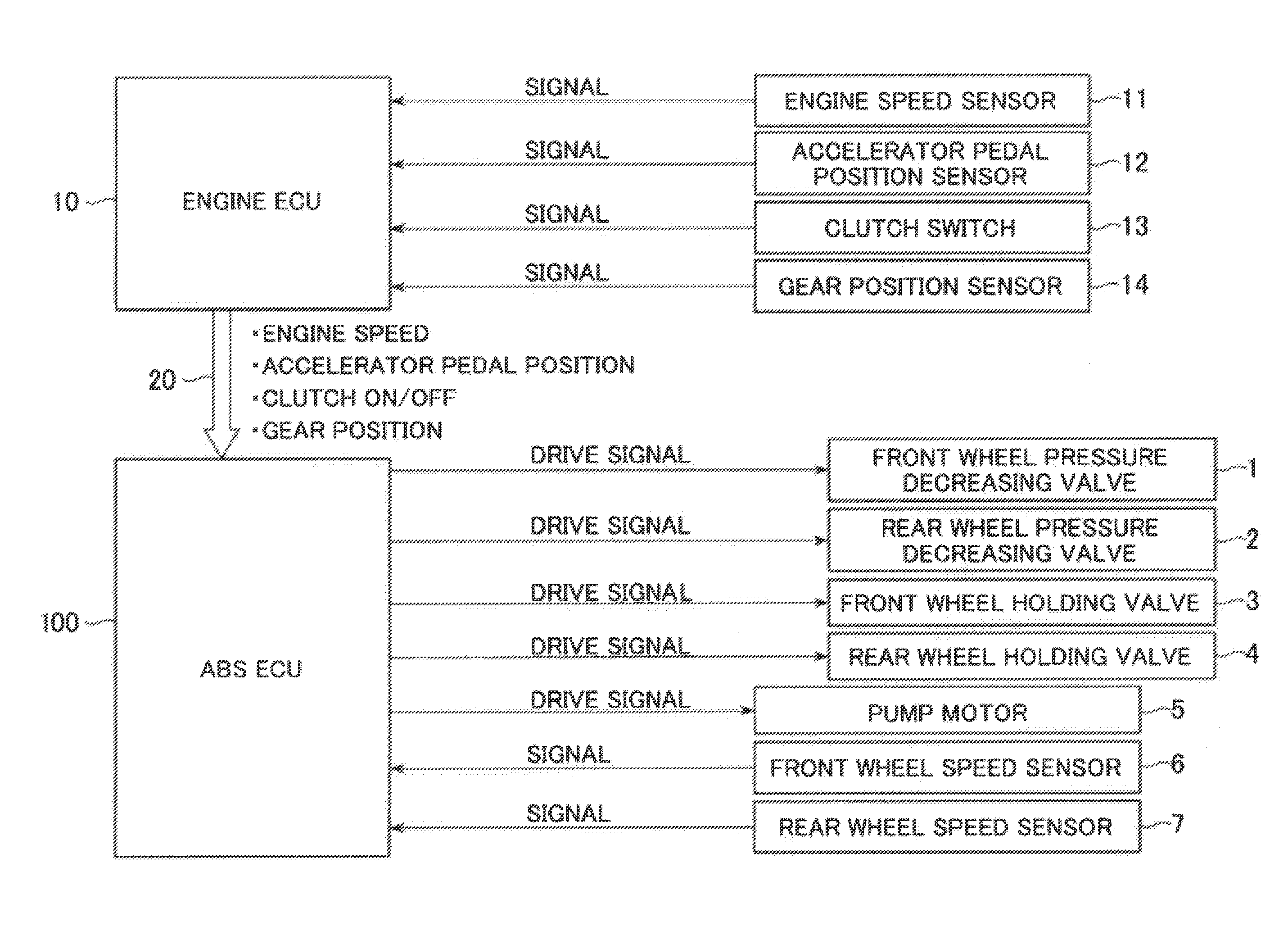
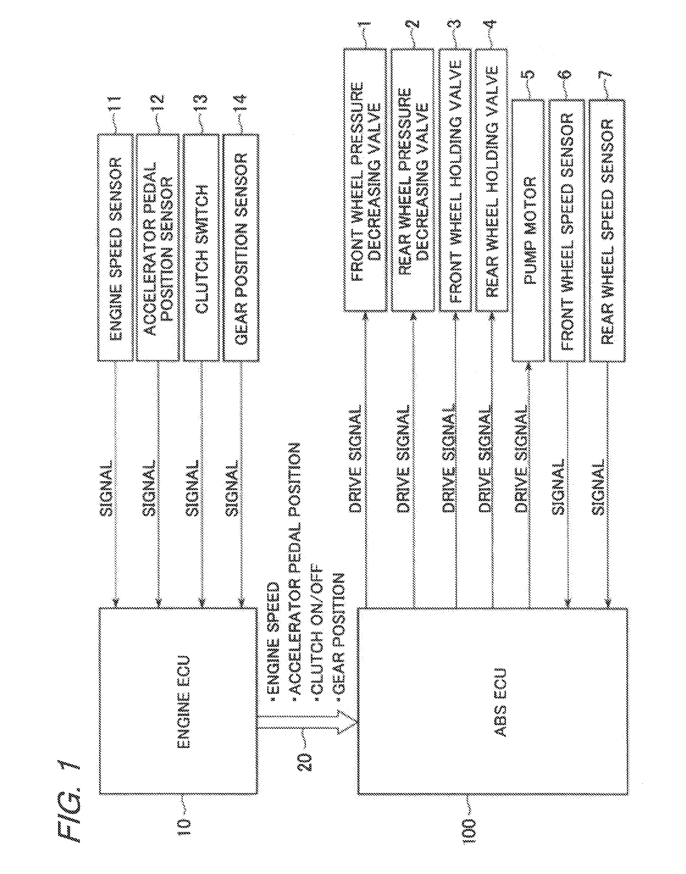
[0020]FIG. 1 is a block diagram showing an ABS-ECU, an engine ECU connected thereto, and so forth.

[0021]The ABS-ECU 100 serving as a vehicle braking force control device is a control device that is mainly installed in a motorcycle vehicle and which, during braking, is for performing antilock brake control of a brake device in order to restore wheel grip at a time when the slip ratio of a wheel has become equal to or greater than a predetermined threshold value. The ABS-ECU 100 is electrically connected, by a connecting line 20, to an engine ECU 10 serving as an engine control unit that controls an engine. The ABS-ECU 100 is electrically connected to a front wheel pressure decreasing valve 1, a rear wheel pressure decreasing valve 2, a front wheel holding valve 3, a rear wheel holding valve 4, a pump motor 5, a front wheel speed sensor 6, and a rear wheel speed sensor 7.

[0022]The front...


PUM


Abstract

A vehicle braking force control device which, at a normal time, performs antilock brake control when the slip ratio of a wheel has become equal to or greater than a predetermined threshold. The control device acquires from the engine control unit an accelerator pedal position signal corresponding to an accelerator pedal position, a clutch connection signal corresponding to a state of connection of a clutch, and a power transmission signal corresponding to a state of power transmission of a transmission. When engine braking is large on the basis of the accelerator pedal position signal, the clutch connection signal, and the power transmission signal, the vehicle braking force control device changes the predetermined threshold value to an offset threshold value that makes it harder to perform the antilock brake control than at the normal time.

Description

BACKGROUND OF THE INVENTION[0001]The present invention relates to a vehicle braking force control device that performs antilock brake control of a brake device.[0002]Conventionally, vehicle braking force control devices that control the hydraulic pressure of brake fluid supplied to a brake device to perform antilock brake control of the brake device have been known. This type of vehicle braking force control device has performed antilock brake control at a time when it has detected wheel slip.[0003]In a vehicle in which a vehicle braking force control device is installed, a braking force resulting from engine braking acts in addition to the braking force resulting from the brake device. In cases where the braking force resulting from engine braking acts, like at times when the brake device has been actuated, the load of the vehicle body moves to the front wheel side, whereby the load on the rear wheel ends up decreasing and the rear wheel ends up in a state where it easily slips. Fo...

Claims


Application Information

Patent Timeline
Patent Type & Authority Patents(United States)
IPC IPC(8): B60T8/176B60T8/1761
CPCB60T8/176B60T8/1761B60T8/17616B60T2201/09B60T2260/04B60W10/06
Inventor OGAWA, TAKAHIROYAMADA, KAZUHIRO
Owner BOSCH CORP
Why Eureka
Try Eureka