Estimating temperature of memory elements

a technology of memory elements and temperature, applied in the field of estimating temperature of memory elements, can solve the problems of not being able to determine the temperature, needing an additional temperature sensor, etc., and achieve the effect of determining the actual temperature more accurately and increasing the temperature dependence of the valu

Active Publication Date: 2014-07-01
NXP BV
View PDF16 Cites 4 Cited by
  • Summary
  • Abstract
  • Description
  • Claims
  • Application Information

AI Technical Summary

Benefits of technology

[0010]The effect of the features of the method according to the invention is that, instead of providing a separate temperature sensor, temperature-dependence of a physical phenomenon is used for determining the temperature. The physical phenomenon that is used is the probability of the assumption of the particular bit value of the plurality of memory elements, after that the assumption has been triggered. It is the insight of the inventor that for particular memory elements the probability of assuming a particular bit value shows a substantial linear dependence on the temperature. A consequence of this is that the contents, after having been read out, of the plurality of memory elements can be easily processed such that a value is determined that is indicative of the temperature.
[0011]An embodiment of the method according to the invention further comprises mapping the value onto the temperature based upon a temperature dependency of the value. This embodiment is very advantageous in applications where the actual temperature has to be determined.
[0020]This method is very advantageous in the situation that the temperature dependency of the probability of assuming a particular bit value is not known or prone to large variability when considering a multiple groups of memory elements. The methods of calibration according to the invention may be followed by the earlier mentioned method for determining a temperature. Calibration before performing the method of estimating the temperature renders it possible to determine the actual temperature more accurately.
[0028]The system provides a convenient implementation for carrying out the method according to the invention. The system benefits from similar advantages as the method according to the invention. Embodiments of the system benefit from similar advantage as the corresponding embodiments of the method according to the invention.
[0030]In another embodiment the trigger circuitry is arranged for triggering the plurality of memory elements by initiating an operating state transition of the plurality of memory elements. In a first variant of this embodiment the plurality of memory elements are SRAM memory cells or flip-flops, and the trigger circuitry is further arranged for initiating the operating state transition by switching the plurality of memory elements from their off-state to their on-state such that the plurality of memory elements assume the bit value. In a second variant of this embodiment the plurality of memory elements are DRAM memory cells, and the trigger circuitry is further arranged for initiating the operating state transition by preventing refreshing of the plurality of memory elements for a predefined period of time such that some of the plurality of memory elements no longer retain the bit-value.

Problems solved by technology

A disadvantage of the known methods and systems for determining the temperature is that they need an additional temperature sensor.
When such temperature sensor is not available or when the one which is available is not functioning properly, no temperature can be determined.

Method used


Image

  • Estimating temperature of memory elements
  • Estimating temperature of memory elements
  • Estimating temperature of memory elements

Examples


first embodiment

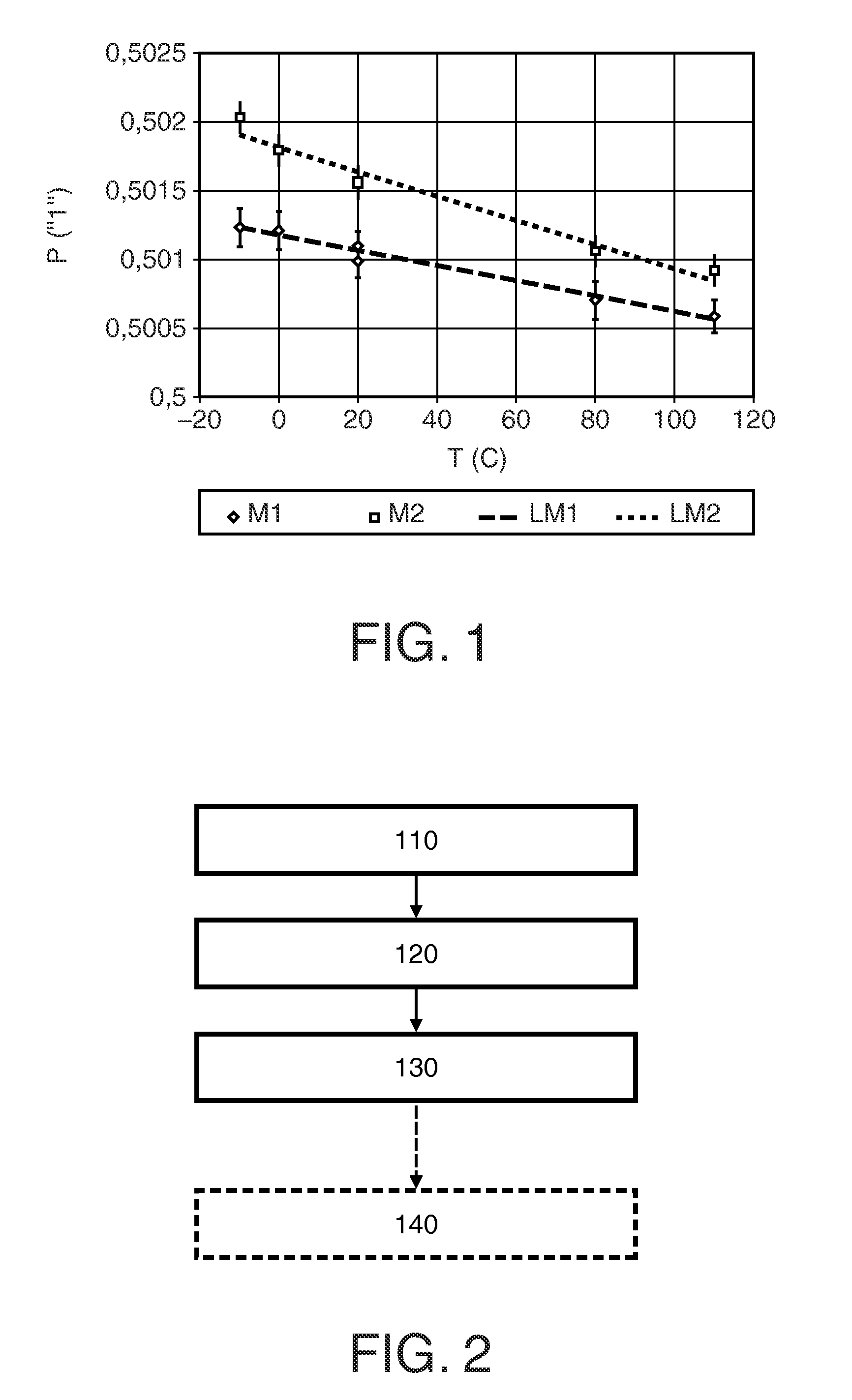
[0043]FIG. 2 shows a flow diagram illustrating the method according to the invention. The method must preferably be applied to a plurality of memory elements wherein at least part of the memory elements has a temperature-dependent probability of assuming a particular bit value. As illustrated above, the memory elements may be selected from the group comprising: an SRAM memory, a DRAM memory, and flip-flops (i.e. D flip-flops).

[0044]A first step 110 of the method comprises the triggering of the assuming of the particular bit value of the plurality of memory elements. The triggering may be done by initiating an operating state transition. For example, the triggering may be done by switching the plurality of memory elements on, if the memory elements are SRAM memory cells or flip-flops. Alternatively, the triggering may be done by letting charge leak away (preventing refresh, so effectively switching the SRAM memory cells off for a while) from DRAM memory cells for a predefined period ...

second embodiment

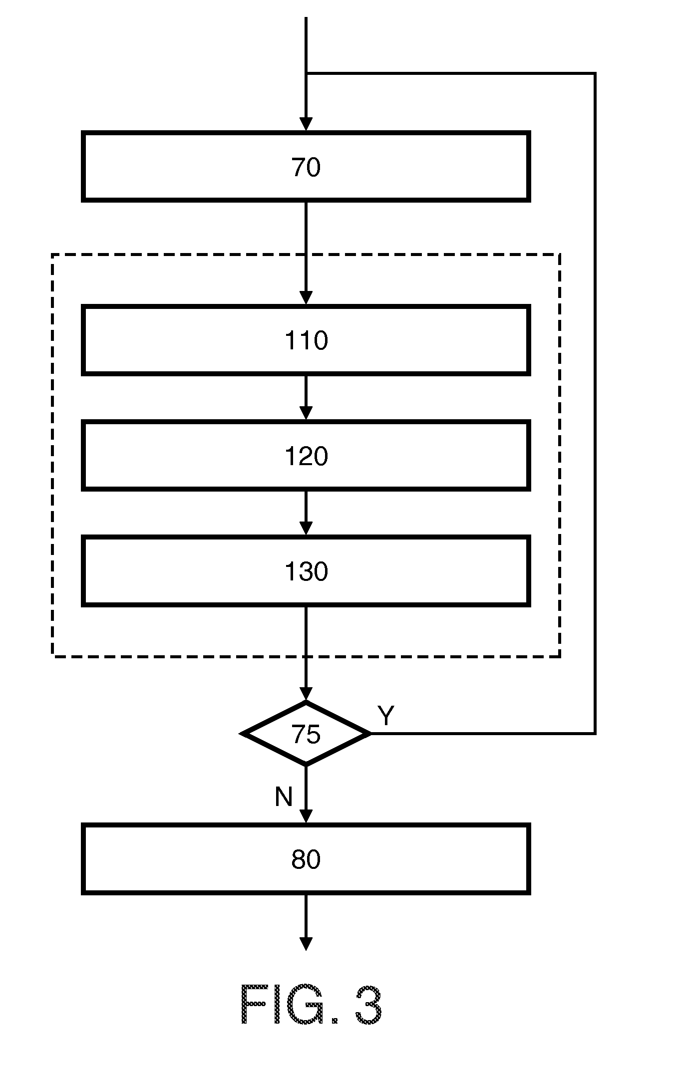
[0048]FIG. 3 shows a flow diagram illustrating the method according to the invention. This embodiment of the method constitutes a method of calibration for determining the dependency, which method comprises the earlier described process steps 110, 120, 130. This sequence of steps is, in this example, repeated for different temperatures. However, if the general shape of a dependency is known, and only the absolute value of the dependency is unknown, the repetition of the process steps is not required. In such situation, the dependency can be simply determined by measuring the value indicative of the temperature at a single temperature, i.e. the environmental temperature of a factory. This particular value together with the known slope of the dependency uniquely determines the dependency. Before the steps 110, 120, 130 are carried out a setting step 70 is carried out in which the temperature is set to a predefined level. After setting of the temperature the steps 110, 120, 130 are car...

third embodiment

[0052]FIG. 6 shows a block diagram of the system according to the invention wherein an implementation of the mapping circuitry 24 is discussed in more detail. It may be advantageous to first perform, before designing the mapping circuitry 24, the method as illustrated in FIG. 3 in order to determine the dependency of the value Vact on the temperature T. Once this dependency is known, it may be stored in a suitable form, i.e. as part of the mapping circuitry 24. In FIG. 6 the dependency is stored in storage means 25. The storage means 25 may be an internal component, but may also be an external component. The mapping circuitry 24 comprises converter circuitry 23 that compares the value Vact with the stored dependency Vact(T) and generates the corresponding temperature T on its output. Alternatively, mapping circuitry 24 may be implemented such that it performs a further function on the value Vact such that the corresponding temperature T is obtained. In order to do so the further fun...


PUM

PropertyMeasurementUnit
temperaturesaaaaaaaaaa
temperatureaaaaaaaaaa

Abstract

The invention relates to a method for determining a temperature (T) of a plurality of memory elements (10) having a temperature-dependent probability (P) of assuming a particular bit value, the method comprising: triggering (110) the plurality of memory elements (10) to assume the particular bit value; reading out (120) the contents of the plurality of memory elements (10) to obtain read data (D), and processing (130) the read data (D) for determining a value (Vact) indicative of the temperature (T). The invention also relates to a program product comprising instructions for causing a processor to perform the method. Such computer program is advantageously used in a smartcard, which then does not need any structural modification at all. The invention further relates to a system for determining a temperature (T) of a plurality of memory elements (10). Such system is advantageously implemented in an integrated circuit, wherein the plurality of memory elements (10) forms part of an integrated memory. The invention provides that temperature (T) can be determined without the need for a separate temperature sensor. The only real requirement is the presence of a plurality of memory elements (10) having a temperature-dependent probability (P) of assuming particular bit value.

Description

FIELD OF THE INVENTION[0001]The invention relates to a method for determining a temperature, a method of calibration, a computer program product comprising instructions for causing a processor to perform any one of these methods, and to a smart card comprising a memory having stored thereon such computer program product. The invention further relates to a system for determining a temperature, and to an integrated circuit comprising such system.BACKGROUND OF THE INVENTION[0002]Methods and systems for determining a temperature are known. In electronic applications where a temperature needs to be determined such method may comprise the provision of a lumped temperature sensor which provides an output value that is indicative of the temperature. In the prior art many different temperature sensors have been reported that may be used in such methods and systems.[0003]A disadvantage of the known methods and systems for determining the temperature is that they need an additional temperature...

Claims


Application Information

Patent Timeline
Patent Type & Authority Patents(United States)
IPC IPC(8): G01K1/00G01K7/42
CPCG01K7/425G01K7/42G01K7/427
Inventor VAN, RIJNSWOU, SANDER, MATTHIJS
Owner NXP BV
Why Eureka
Try Eureka