Apparatuses, systems, and methods for apparatus operation and remote sensing

a technology for remote sensing and apparatus, applied in the field of methods, apparatuses, and systems for apparatus operation and remote sensing, can solve the problems of less effective prediction, imperfect prediction, and less effective prediction than in other situations, and achieve the effect of reducing the required bandwidth

Active Publication Date: 2014-07-08
CARNEGIE MELLON UNIV
View PDF29 Cites 20 Cited by
  • Summary
  • Abstract
  • Description
  • Claims
  • Application Information

AI Technical Summary

Benefits of technology

[0013]The present invention will generally be described in terms reducing or eliminating the apparent latency in the transmission of a real-time data from a sensor to a control agent. In some embodiments of the invention the latency is not actually reduced, although the present invention makes it appear to the operator that the latency has been reduced or eliminated. Alternatively, this aspect of the present invention may be considered to be latency compensation. In particular, prediction of future events is used to compensate for latency in the system. However, as will be described in more detail hereinbelow, prediction is not perfect and in some situations the prediction is less effective than in other situations. For example, when driving around a corner into unknown terrain or in other situations in which the data is unknown or incomplete, the prediction will be less effective.
[0014]The control agent may be a person (e.g., a human operator) or a device, such as a control system for an autonomous apparatus. The sensor will generally be moving with respect to the scene, and the scene may or may not be static. In other words, elements of the scene may or may not move with respect to each other and with respect to the sensor. In some embodiments, elements such as cars and people may be moving in the scene. In other embodiments, only the apparatus and sensors are moving in the scene. If the scene is generally static, the sensor may only send data when changes are detected, thereby reducing bandwidth usage. If the scene is not static, the sensor may continue to update the data to capture scene motion.
[0015]In one embodiment, the present invention is related to remote apparatus operation and remote sensing, as well as to related operations and technologies. The present invention has many applications and many advantages over the prior art including providing for the reduction or elimination of latency in remote apparatus operations, providing for a reduction in required bandwidth, providing improved data compressions, and providing for de-coupled video between a apparatus and an operator located remote from the apparatus.

Problems solved by technology

However, as will be described in more detail hereinbelow, prediction is not perfect and in some situations the prediction is less effective than in other situations.
For example, when driving around a corner into unknown terrain or in other situations in which the data is unknown or incomplete, the prediction will be less effective.

Method used


Image

  • Apparatuses, systems, and methods for apparatus operation and remote sensing
  • Apparatuses, systems, and methods for apparatus operation and remote sensing
  • Apparatuses, systems, and methods for apparatus operation and remote sensing

Examples


Embodiment Construction

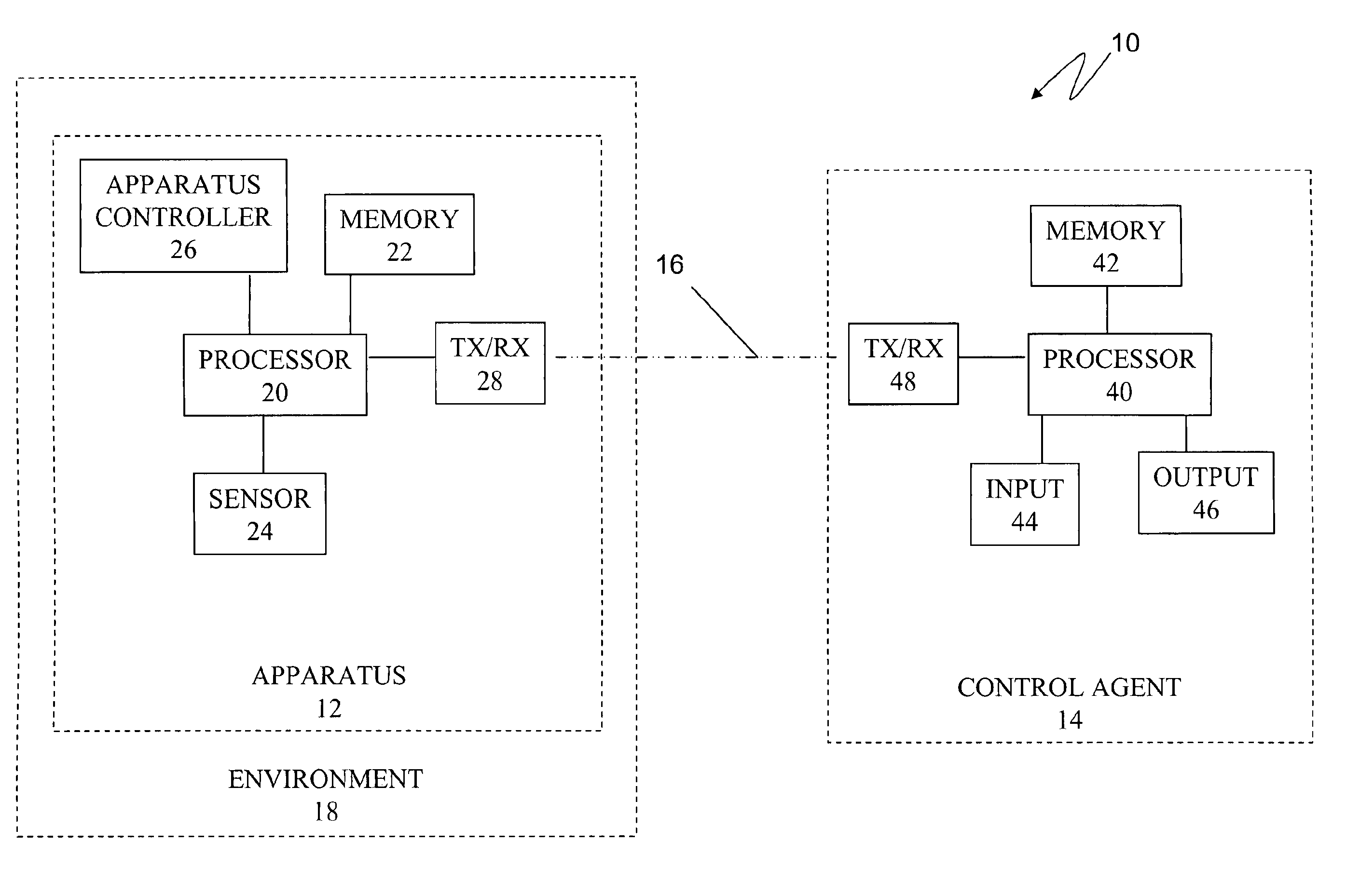
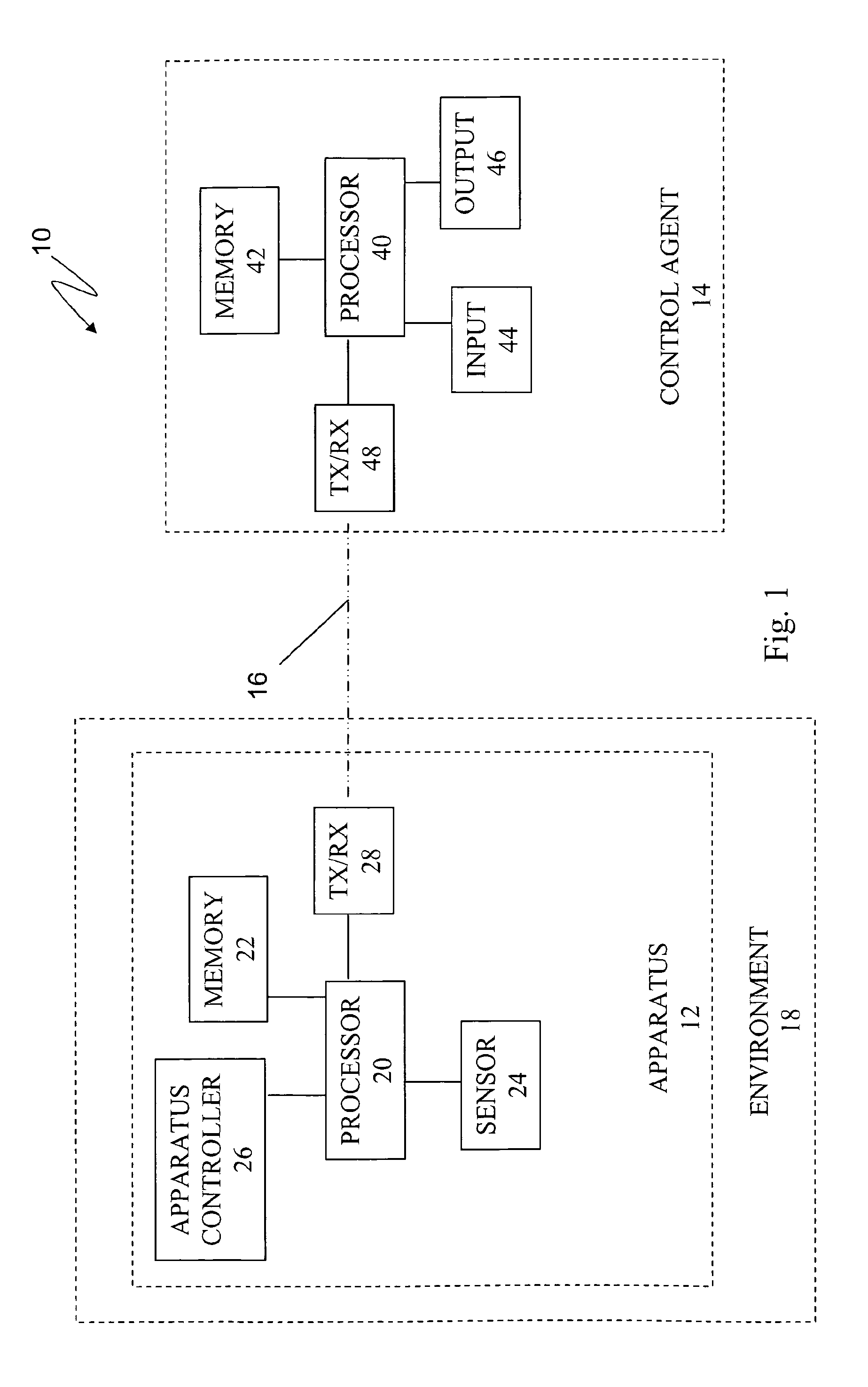
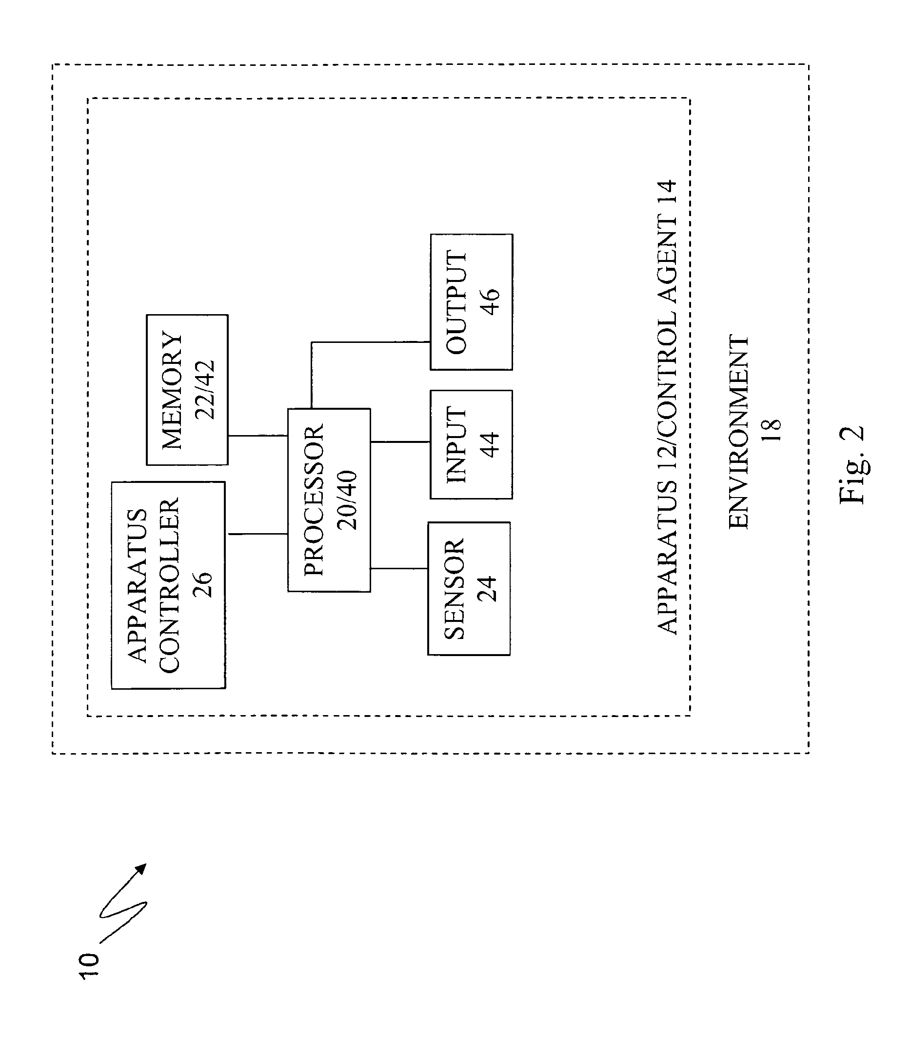
[0045]FIG. 1 illustrates a system 10 according to one embodiment of the present invention. The system 10 includes a apparatus 12 and an control agent 14. In the illustrated embodiment, the apparatus 12 is separate from the control agent 14, and the apparatus 12 and control agent 14 are connected via a communications link 16. In this embodiment, the apparatus is referred to as a “remote apparatus”12 because it is separated from the control agent. However, in other embodiments of the system 10, the control agent is within the apparatus 12, in which case the apparatus 12 is not a “remote” apparatus. Furthermore, the communications link 16 will generally be described in terms of a wireless communications link 16, although the present invention may also be used with communications links over physical media, such as electrical conductors and optical fibers. Also, the communications link 16 may be more than one communications link to allow, for example, for redundancy or increased bandwidt...


PUM


Abstract

A method and system for controlling an apparatus including receiving data indicative of an actual state of the apparatus, defining a first viewpoint relative to at least one of the environment and the apparatus, determining a first predicted state of the apparatus at time T, determining a first predicted state of the environment at time T, producing a first virtualized view from the first viewpoint, sending a first control signal to the apparatus after producing the first virtualized view, defining a second viewpoint relative to at least one of the apparatus and the environment, determining a second predicted state of the apparatus at time T+delta T, determining a second predicted state of the environment at time T+delta T, producing the second virtualized view from the second viewpoint, sending a second control signal to the apparatus after producing the second virtualized view, and changing the actual state of the apparatus based on the first control signal.

Description

CROSS-REFERENCE TO RELATED APPLICATIONS[0001]This application claims priority from U.S. Provisional Patent Application No. 61 / 011,854, filed Jan. 22, 2008, which is incorporated herein by reference.STATEMENT REGARDING FEDERALLY-SPONSORED RESEARCH AND DEVELOPMENT[0002]This invention was made, in part, with government support under contract W56HZV-04-C-0745 entitled “Improved Situational Awareness through Colorized Ranging”, and awarded by DCS Corporation under contract from TARDEC, part of the U.S. Army Research, Development and Engineering Command (RDECOM). The United States government may have certain rights in this invention.FIELD OF THE INVENTION[0003]The present invention is directed generally to methods, apparatuses, and systems for apparatus operation and remote sensing, and for the creation of synthetic views and virtual windows in applications related to apparatus operation and remote sensing.BACKGROUND OF THE INVENTION[0004]Remote apparatus operation and remote sensing are ...

Claims


Application Information

Patent Timeline
Patent Type & Authority Patents(United States)
IPC IPC(8): G08B17/00G05B23/02
CPCG05B23/0267
Inventor KELLY, ALONZO JAMESHERMAN, HERMANRANDER, PETER WILLIAMWARNER, RANDON
Owner CARNEGIE MELLON UNIV
Why Eureka
Try Eureka