Hybrid flow blade design

a blade and hybrid technology, applied in the field of turbines, can solve the problems of reducing the efficiency of the turbine, leakage flow through the cavity between rotating parts and stationary parts, etc., and achieve the effect of reducing leakage loss

Active Publication Date: 2014-07-15
GE INFRASTRUCTURE TECH INT LLC
View PDF7 Cites 10 Cited by
  • Summary
  • Abstract
  • Description
  • Claims
  • Application Information

AI Technical Summary

Benefits of technology

[0003]Airfoils according to embodiments of this invention result in a hybrid controlled flow concept that reduces leakage loss by creating a different vortexing concept near endwall regions of the airfoils than at the core region of the airfoils. Specifically, a turbine static nozzle airfoil is disclosed having a variable, non-linear, throat dimension, s, divided by a pitch length, t, distribution (“s / t distribution”) across its radial length. In one embodiment, a plurality of static nozzle airfoils are provided, with each static nozzle airfoil configured such that a throat distance between adjacent static nozzle airfoils is larger proximate the hub regions of the airfoils than proximate the core regions of the airfoils, and the throat distance between adjacent static nozzle airfoils is smaller proximate the tip regions of the airfoils than proximate the core regions.

Problems solved by technology

During this process, leakage flow through the cavities between rotating parts and stationary parts can reduce turbine efficiency because of the amount of leakage flow and the intrusion loss from the interaction of the core flow and leakage flow.

Method used


Image

  • Hybrid flow blade design
  • Hybrid flow blade design
  • Hybrid flow blade design

Examples


Embodiment Construction

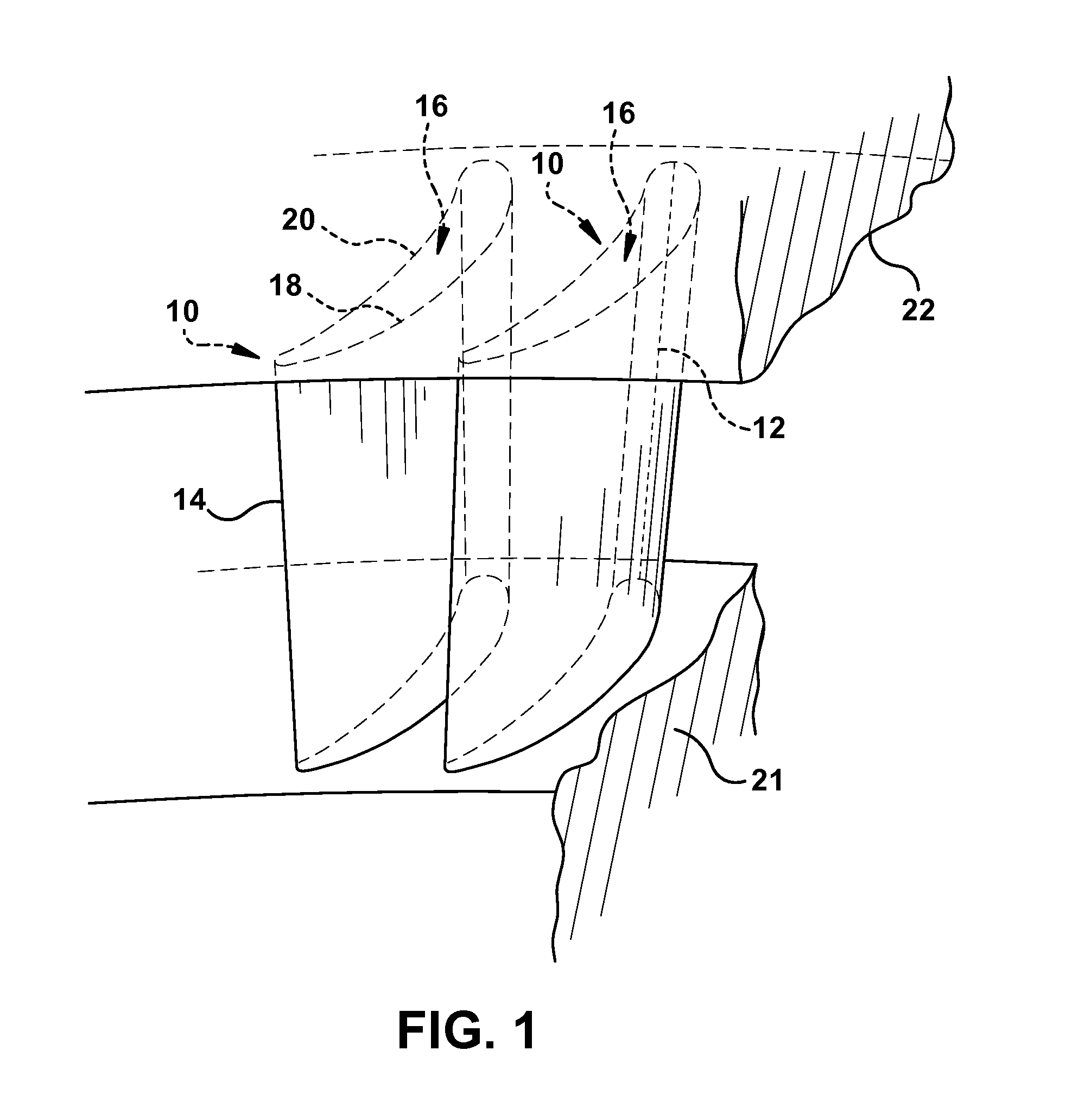
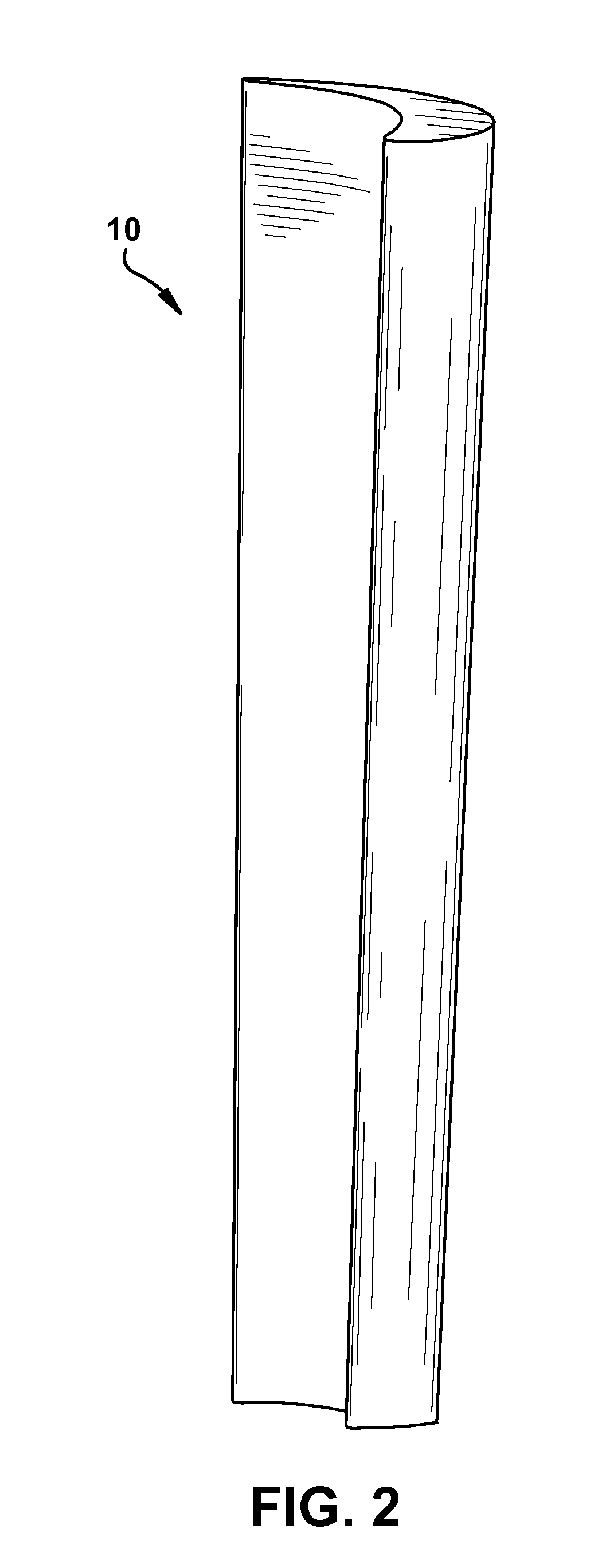
[0014]Turning to FIG. 1, a three-dimensional perspective view of two adjacent static nozzle airfoils 10 as known in the art is shown. Static nozzle airfoil 10 (also referred to as blade 10) includes a leading edge 12 and a trailing edge 14 opposing leading edge 12. Static nozzle airfoil 10 further includes a body portion 16 located between leading edge 12 and trailing edge 14. Body portion 16 includes a convex suction side 18 and a concave pressure side 20 opposing suction side 18. Another view of a nozzle airfoil 10 as known in the art is shown in FIG. 2. As will be discussed in more detail herein (and illustrated in FIG. 5), nozzle airfoil 10 is referred to as a free vortex nozzle because it has an s / t distribution (throat dimension divided by the pitch length) that linearly increases with radius at a specific rate.

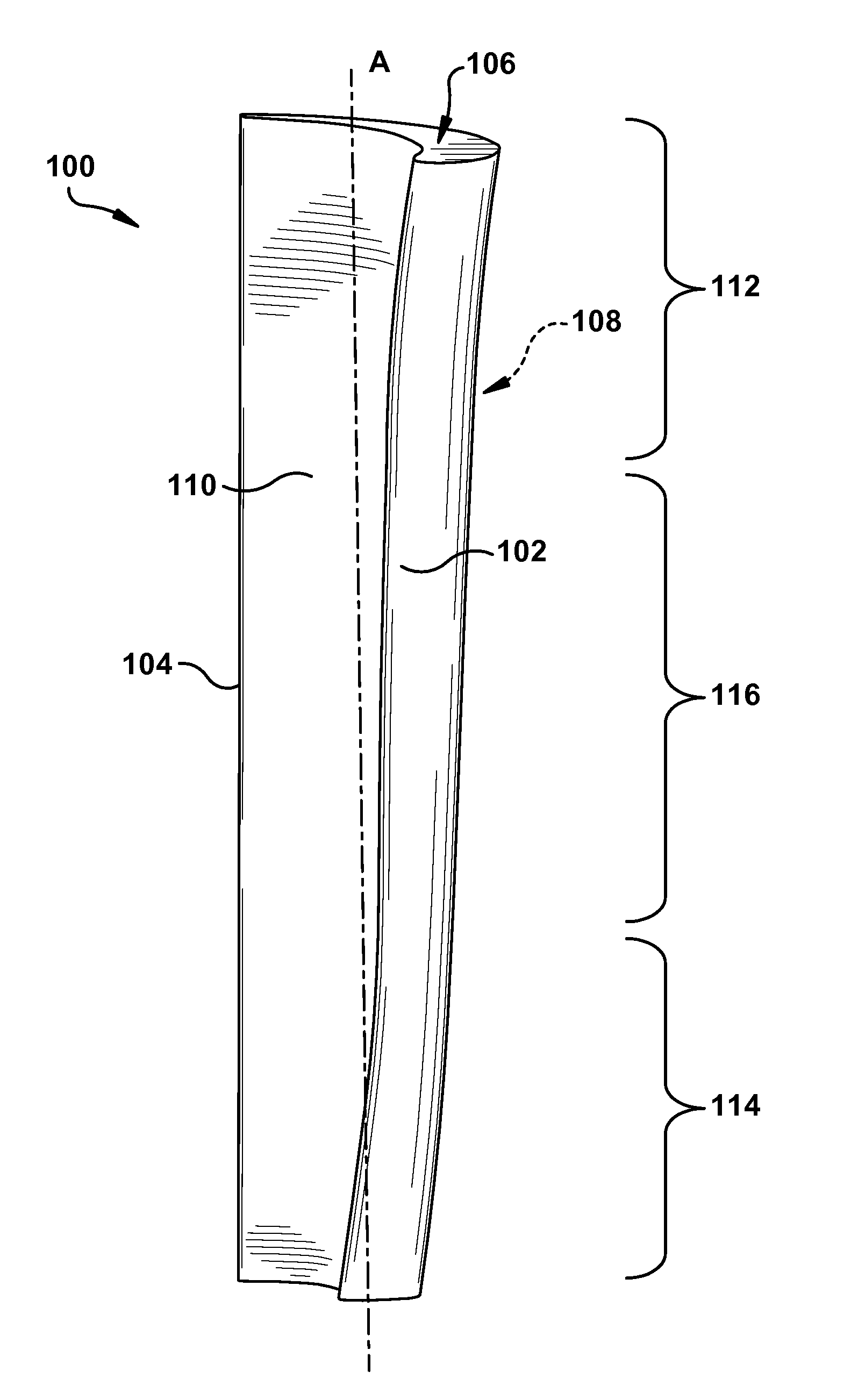
[0015]Turning to FIG. 3, a three-dimensional perspective view of a static nozzle airfoil 100 is shown according to an embodiment of this invention. As discussed in more...


PUM


Abstract

Airfoils according to embodiments of this invention result in a hybrid controlled flow concept that reduces leakage loss by creating a different vortexing concept near endwall regions of the airfoils than at the core region of the airfoils. Specifically, a turbine static nozzle airfoil is disclosed having a variable, non-linear, throat dimension, s, divided by a pitch length, t, distribution (“s / t distribution”) across its radial length. In one embodiment, a plurality of static nozzle airfoils are provided, with each static nozzle airfoil configured such that a throat distance between adjacent static nozzle airfoils is larger proximate the hub regions of the airfoils than proximate the core regions of the airfoils, and the throat distance between adjacent static nozzle airfoils is smaller proximate the tip regions of the airfoils than proximate the core regions.

Description

BACKGROUND OF THE INVENTION[0001]The subject matter disclosed herein relates to a turbomachine. Specifically, the subject matter disclosed herein relates to stationary blade design that results in a hybrid vortexing flow as operating fluid moves through the turbomachine.[0002]Turbines (e.g., steam turbines or gas turbines) include static nozzle (or “airfoil”) segments that direct flow of a working fluid into turbine buckets connected to a rotor. A complete assembly of nozzle segments is sometimes referred to as a diaphragm stage (e.g., a diaphragm stage of a steam turbine), where a plurality of stages form a diaphragm assembly. The diaphragm assembly is designed to convert thermal energy of the working fluid to tangential momentum that is used to drive the bucket and rotor. During this process, leakage flow through the cavities between rotating parts and stationary parts can reduce turbine efficiency because of the amount of leakage flow and the intrusion loss from the interaction o...

Claims


Application Information

Patent Timeline
Patent Type & Authority Patents(United States)
IPC IPC(8): F01D9/02
CPCF01D5/141
Inventor ZENG, XIAOQIANGSLEPSKI, JONATHON EDWARD
Owner GE INFRASTRUCTURE TECH INT LLC
Why Eureka
Try Eureka