
Abrasive single-crystal turbine blade

A turbine blade and wear-resistant technology is applied in the field of manufacturing of wear-resistant single crystal turbine blades to achieve the effects of reducing leakage loss, optimizing service life and improving efficiency

Active Publication Date: 2011-05-11
ANSALDO ENERGIA IP UK LTD
View PDF10 Cites 12 Cited by
  • Summary
  • Abstract
  • Description
  • Claims
  • Application Information

AI Technical Summary

Problems solved by technology

However, it has been known since the beginning of the 90s (see, for example, document DE 10 2004 059 904 A1) to use laser overlay welding (Laserauftragsschweissen) (English: Laser Metal Forming (Laser Metal Forming), abbreviated LMF) for the construction of abrasive blade tips , however, this method is rarely used in industry standard

Method used


Image

  • Abrasive single-crystal turbine blade
  • Abrasive single-crystal turbine blade
  • Abrasive single-crystal turbine blade

Examples


Embodiment Construction

[0050] Below will be according to embodiment and Figures 1 to 5 The present invention is explained in detail.

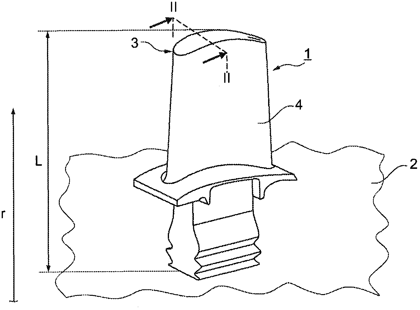
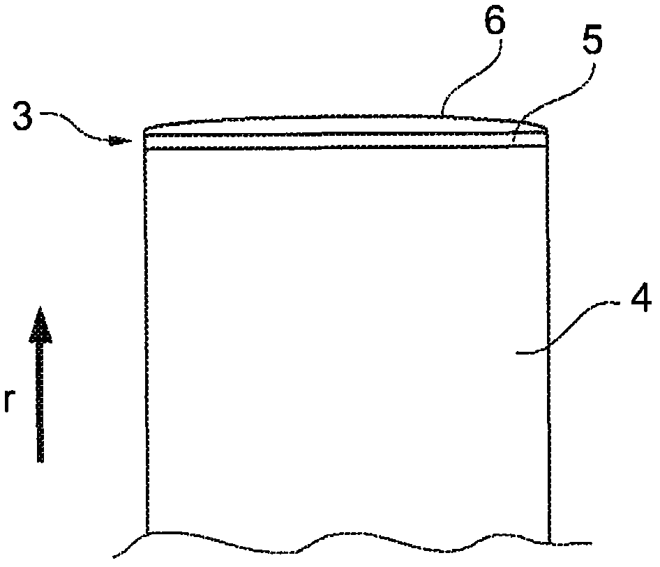
[0051] figure 1 A turbine blade 1 of a (only schematically sketched here) rotor 2 for a gas turbine is shown in a perspective view, while figure 2 Shown in enlarged form along the figure 1 The cross-section of the line II-II. The turbine blade 1 has a monocrystalline base body 4 extending in the radial direction r (relative to the rotor), which base body 4 has, according to the invention, an epitaxial, oxidation-resistant intermediate coating applied by LMF at the blade tip 3 5, the intermediate coating 5 has an anti-wear and anti-oxidation coating 6 applied thereon (see figure 2 ). In this case, the coating 6 covers the entire intermediate coating 5 , but it is equally possible that the coating 6 only partially covers the intermediate coating 5 . The basic material of the blade base body is, for example, a single crystal nickel-based superalloy. In this fi...


PUM

PropertyMeasurementUnit
Temperatureaaaaaaaaaa

Abstract

The invention relates to an abrasive single-crystal turbine blade, in detail, relates to a turbine blade (1) used for a turbine rotor (2).A turbine blade for a turbine rotor, is provided having a single-crystal basic body which has a blade tip and extends in the radial direction. The turbine blade includes at least one oxidation-resistant intermediate coating, which is applied by laser metal forming and is epitaxially bonded to the basic body, is arranged on the radially outer blade tip, and in that an at least single-layer, wear-resistant and oxidation-resistant coating, which is applied by laser metal forming and consists of oxidation-resistant binder material and abrasive particles embedded therein, is arranged on at least certain regions of said epitaxial intermediate coating.

Description

technical field [0001] The invention relates to the fields of gas turbine technology and material technology. The invention relates to abrasive (abrasiv) single-crystal turbine blades (Turbinenschaufel) with high resistance to oxidation and friction and wear and to a production method for abrasive single-crystal turbine blades of this type. Background technique [0002] Reducing leakage losses in turbines has been the object of intensive research and development work for decades. During the operation of a gas turbine, relative motion between the rotor and the casing is unavoidable. The resulting wear of the casing or of the blades results in the sealing effect being no longer provided. As a solution to this problem, a combination of an abradable thick coating on the heat shield and a protective coating on the blade tip is provided. [0003] It has been known since the 1970s to apply an additional coating to the blade tip or to increase the wear resistance by suitable modi...

Claims


Application Information

Patent Timeline
IPC IPC(8): F01D5/28B32B15/04B23K26/34B23K26/42
CPCB23K26/34B23K35/304B23K35/327B23K2101/001B23K2101/34B23K2103/08C23C26/00C23C28/3215C23C28/34C23C28/347C30B13/24C30B29/52F01D5/005F01D5/20F01D5/28F01D5/286F01D5/288F01D11/12F01D11/14F05D2230/31
Inventor M·霍贝尔A·施内尔Y·佩拉顿
Owner ANSALDO ENERGIA IP UK LTD
Learn More