Turbine engine and a method for cooling a turbine engine

a technology of turbine engine and cooling method, which is applied in the direction of machines/engines, liquid fuel engines, mechanical equipment, etc., can solve the problems of reduced operational dependability and reliability, difficult supply of coolant to individual blades in the various rows of blades, and high production cost of conduction of coolant, so as to increase the service life of the elements and the reliability of the turbine engine. , the effect of increasing the efficiency of the turbine engin

Inactive Publication Date: 2006-11-07
SIEMENS AG
View PDF9 Cites 11 Cited by
  • Summary
  • Abstract
  • Description
  • Claims
  • Application Information

AI Technical Summary

Benefits of technology

[0009]The object of the present invention is to increase the efficiency of the turbine engine at an economically justifiable cost and at the same time to reduce the operating risk and to increase the service life of the elements and the reliability of the turbine engine.
[0011]The invention is based on the calculation that the operating risk can be reduced by simplifying the coolant feed to the blades. The resulting advantageous reduction in the number of seals and simultaneous shortening of the remaining length of sealing increases operational dependability, lowers the probability of failure and reduces leakage losses of the coolant. In addition, simpler sealing systems can be used which likewise reduce the operating risk. Multiple coolants of differing quality flow in the individual cavities between two adjacent disks; these are “fresh” coolants like fresh air and / or live steam which are conducted to the blades and / or “used” coolants like used air and / or used steam which are conducted away from the blades. The simple and reliable provision of coolants permits the efficient use of said coolants and consequently enables a profitable increase in efficiency, since the components exposed to the working medium withstand higher temperatures.
[0012]Extremely advantageous is the arrangement of the invention such that the radially adjacent cavities are sealed front one another by means of centrifugal force based seals. This extremely reliable method of sealing radially adjacent areas reduces the leakage loses in the coolant.
[0013]An absolutely tight and secure connection is advantageously obtained if the integrated coolant channels of each blade arranged on one and the same disk communicate via a radial bore or passage with one and the same cavity which is enclosed by means of an adjacent disk.
[0017]The invention thus constitutes a radial multilayered system of areas shielded from one another, in which differing pressures prevail. At the same time, a pressure difference applies radially, viewed from the inside to the outside. The greatest pressure, caused by live steam, applies in the innermost cavity, viewed radially, of two adjacent disks, the next lowest pressure, caused by used steam, in the next cavity radially further outward, the next lowest pressure, caused by fresh air, in the outermost cavity, and the lowest pressure, caused by the working medium, applies in the flow channel which is arranged between turbine shaft and stator. Advantageous are the short sealing lengths running between the disks in a circumferential direction coupled with the low number of sealing elements and the beneficial layered arrangement of coolants of differing pressure which enable profitable partial reuse of the leakage flow.

Problems solved by technology

However, steam places higher demands on the sealing of the complete cooling system, which means higher production costs with regard to conduction of the coolant.
Disadvantageous here is the enormous economic and technological outlay required for this purpose, which on top of everything leads to a reduction in operational dependability and reliability on account of the complicated technology.
Supplying coolant to individual blades in the various rows of blades is very difficult, due to the arrangement of the individual elements concerned, and demands a high outlay in order to guarantee the required sealing of the system and a low operating risk.

Method used


Image

  • Turbine engine and a method for cooling a turbine engine
  • Turbine engine and a method for cooling a turbine engine

Examples


Embodiment Construction

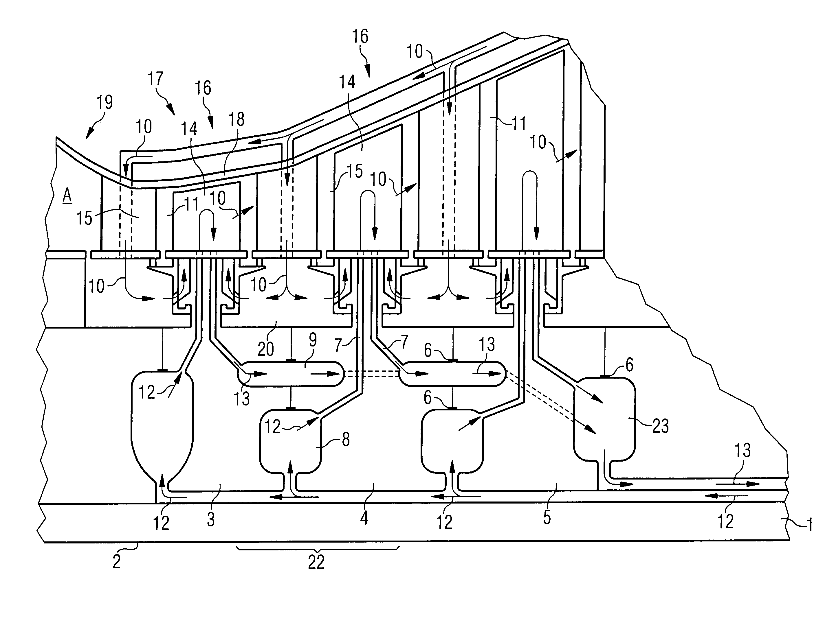
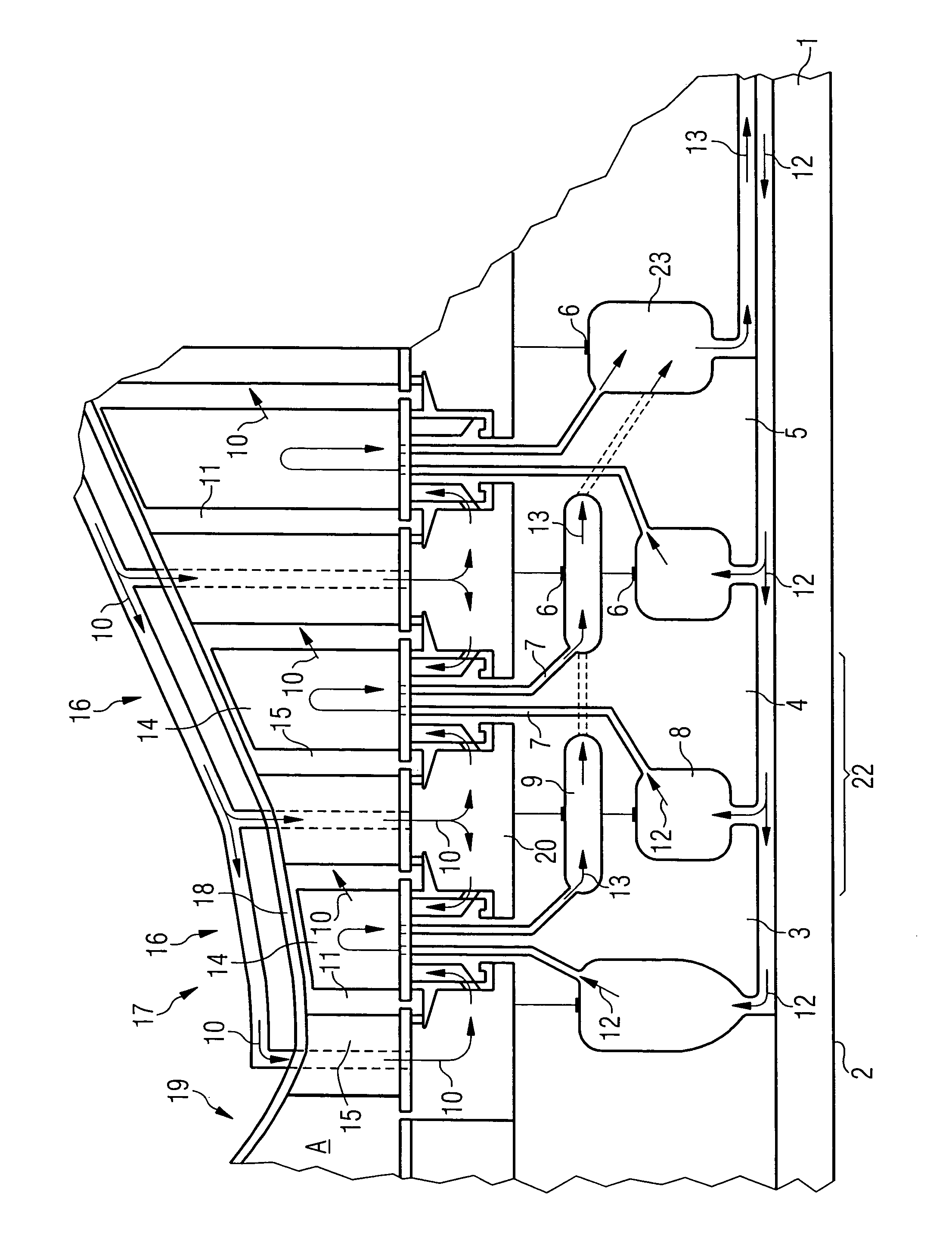
[0020]The single FIGURE in the drawings shows a section through a gas turbine 17 along the axis of rotation 2 of the turbine shaft 1. Arranged adjacently on the turbine shaft 1 are the disks 3, 4 and 5. Fastened to each of these disks 3, 4 and 5 are blades 14 grouped in blade rings 16 of the first, second and third turbine stage. Each turbine stage is formed by a vane ring mounted on the stator 18 in conjunction with a blade ring 16 downstream of this vane ring, viewed in the direction of flow of the working medium A. Also, the guide vanes 15 are supplied with fresh air via an external supply not shown, which is represented by the direction-of-flow arrows 10.

[0021]The partially shown combustion chamber 19 of the gas turbine 17 runs into the flow channel 11 of the working medium A. During operation of the gas turbine 17, the working medium A flows, coming from the combustion chamber 19, through the flow channel 11. As it does so, it flows past guide vanes 15 and performs work on the ...


PUM


Abstract

A turbine engine with a turbine shaft which has a number of disks arranged adjacent to one another, to each of which a number of blades are fastened in a star arrangement, wherein these blades can be cooled with at least one coolant which flows through coolant channels inside the blades is provided.

Description

CROSS REFERENCE TO RELATED APPLICATIONS[0001]This application claims priority to European application No. 02023472.0 EP, filed Oct. 21, 2002, and which is incorporated by reference herein in its entirety.FIELD OF INVENTION[0002]The invention relates to a turbine engine having a turbine shaft which has a number of adjacently arranged disks to each of which a number of blades can be fastened in a star arrangement, wherein said blades can be cooled by means of at least one coolant which flows through coolant channels inside the blades, and to a method for cooling these blades.BACKGROUND OF INVENTION[0003]Turbine engines are used in many fields, principally as drives in the aviation industry and for energy production. In energy production, a distinction is made between gas turbines and steam turbines, which are both used, often simultaneously in so-called gas and steam installations, for driving generators. In the gas turbine, which is examined below, a fuel / air mixture is ignited in a ...

Claims


Application Information

Patent Timeline
Patent Type & Authority Patents(United States)
IPC IPC(8): F01D5/08F01D5/18F01D25/12F01K23/10F02C7/18
CPCF01D5/084F01D5/085Y02E20/16Y02T50/676F05D2260/2322F05D2260/205Y02T50/60
Inventor TIEMANN, PETER
Owner SIEMENS AG
Why Eureka
Try Eureka