Electric storage device monitor

a technology of electric storage device and monitor, which is applied in the direction of electrochemical generators, cell components, instruments, etc., can solve the problems that the battery monitor cannot receive the actuation signal from the load side, and other elements than the secondary

Active Publication Date: 2014-07-15
GS YUASA INT LTD
View PDF16 Cites 111 Cited by
  • Summary
  • Abstract
  • Description
  • Claims
  • Application Information

AI Technical Summary

Problems solved by technology

However, if the secondary battery is separated from the load to be used or an error or a problem occurs in the communication between the secondary battery and the load, the battery monitor cannot receive the actuation signal from the load side.
This kind of problem occurs in other elements than the secondary battery, for example, capacitors.

Method used


Image

  • Electric storage device monitor
  • Electric storage device monitor
  • Electric storage device monitor

Examples


first embodiment

[0018]A first embodiment will be described with reference to FIGS. 1 to 4.

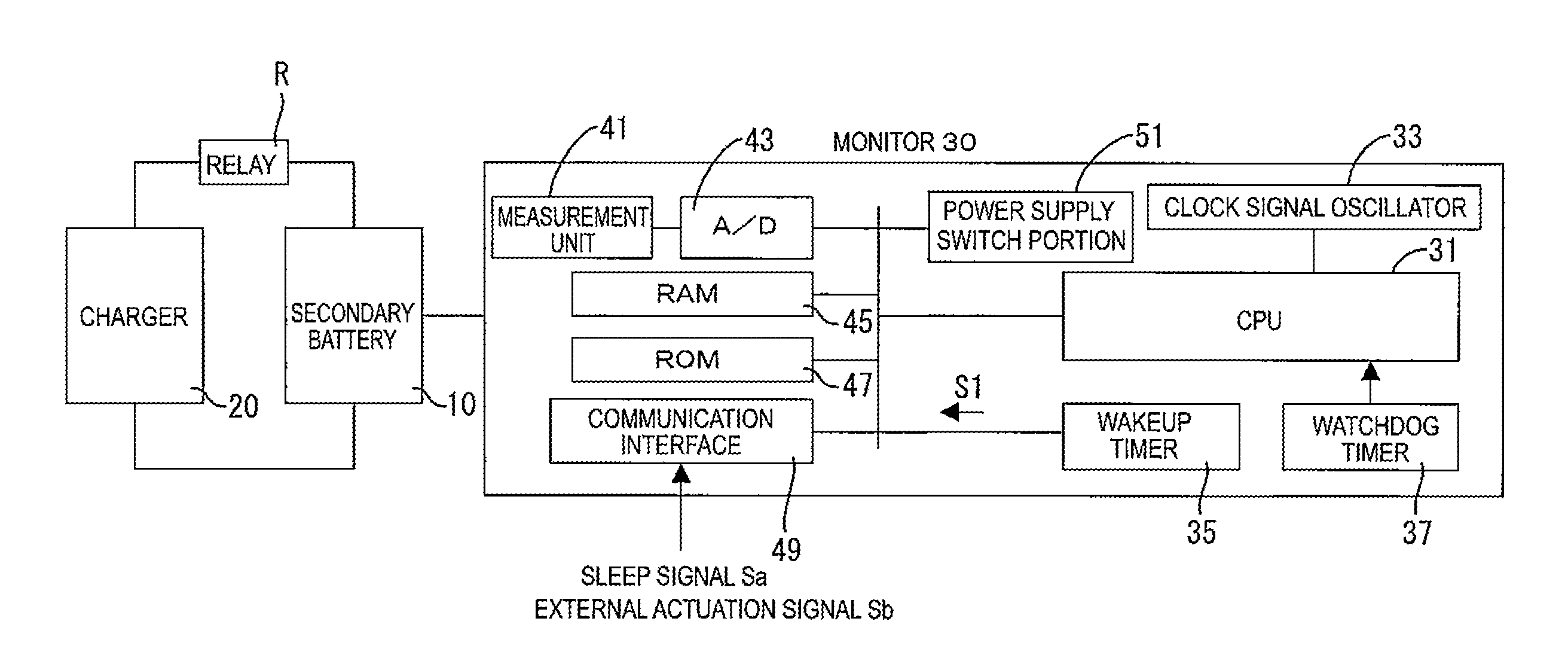
[0019]A monitor 30 is connected to a secondary battery 10 and integrally provided therewith. The secondary battery 10 is an example of an electric storage device. The monitor 30 monitors a state of the secondary battery 10, specifically, voltage, temperature, and current values of the battery. As illustrated in FIG. 1, the monitor 30 includes a CPU 31, a clock signal oscillator 33, a wakeup timer 35, a watchdog timer 37, a measurement unit 41, an A / D converter 43, a RAM 45, a ROM 47, and a communication interface 49 and a power supply switch portion 51. The CPU 31 is an example of a control unit and the RAM 45 is an example of a memory.

[0020]The measurement unit 41 detects voltage (inter-terminal voltage), temperature, and current values of the secondary battery 10. The A / D converter 43 converts detected values of the voltage, the temperature, and the current of the secondary battery 10 into digital values and...

second embodiment

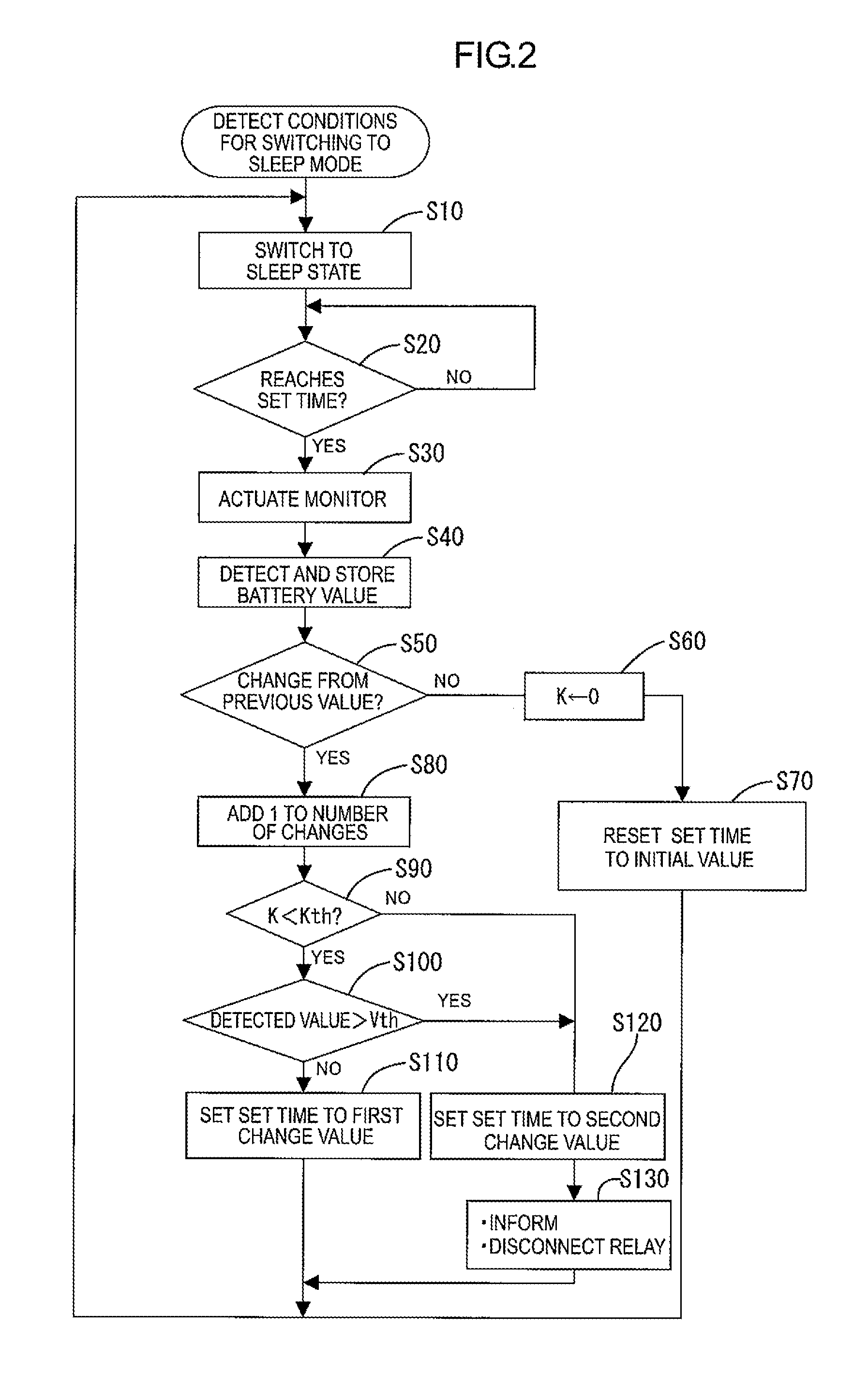
[0045]Next, a second embodiment will be described with reference to FIGS. 5 to 7. In the first embodiment, the voltage of the secondary battery 10 proportionally changes with respect to the time axis and changes the actuation period T of the monitor 30 from 60 seconds to 30 seconds.

[0046]In the second embodiment, the CPU 31 compares the current detected voltage and the previous detected voltage and obtains a change amount of the battery voltage every time determining that the current voltage changes from the previous voltage. Specifically, if determining that the current detected voltage changes from the previous detected voltage (S50: Yes), the CPU 31 computes a change amount between the previous detected voltage and the current detected voltage (S210). As the change amount becomes greater, the CPU 31 changes the set time of the wakeup timer 35 to be a shorter value (S220). Accordingly, the greater the change amount of the detected battery voltage values is, the shorter the actuati...

third embodiment

[0048]Next, a third embodiment will be described with reference to FIG. 8. An actuation period change sequence of the third embodiment is substantially same as the sequence of the second embodiment including steps S10 to S220 and additionally includes processing of S3 and S5 in FIG. 7. Therefore, the processing of S3 and S5 will be explained.

[0049]As shown in FIG. 8, in the third embodiment, if the CPU 31 detects that the conditions for switching the monitor 30 to the sleep mode are satisfied and receives the sleep signal Sa output from the load side, the CPU 31 of the monitor 30 determines whether the most recent battery voltage of the secondary battery 10 detected in the measurement mode is close to a full-charge voltage or not (S3). Specifically, the CPU 31 compares the most recent battery voltage to a threshold voltage Vth that is previously set (a value close to the full-charge voltage). If determining that the most recent battery voltage is higher than the threshold voltage Vt...


PUM


Abstract

An electric storage device monitor includes a measurement unit detecting and obtaining a detected value, a power supply switch portion switching a power supply state of the monitor between a monitoring state and a low power consumption state, a wakeup timer to which an actuation time is set and starting counting time in response to switching to the low power consumption state and continuing counting time and outputting an actuation signal if reaching the actuation time, and a control unit. The switch portion switches from the low power consumption state to the monitoring state every time the wakeup timer outputs the actuation signal. The control unit controls the measurement unit to detect and obtain the detected value in the monitoring state, compares the detected value and a reference value, and changes the actuation time according to a comparison result of the detected value and the reference value.

Description

CROSS REFERENCE TO RELATED APPLICATION[0001]This application claims priority from Japanese Patent Application Nos. 2011-197077 filed on Sep. 9, 2011, 2012-176839 filed on Aug. 9, 2012, and 2012-197187 filed on Sep. 7, 2012. The entire contents of the priority applications are incorporated herein by reference.FIELD OF THE INVENTION[0002]The present invention relates to a technology of monitoring a state of an electric storage device.BACKGROUND OF THE INVENTION[0003]A battery monitor executes a voltage measurement mode and a sleep mode alternately to reduce power consumption of a secondary battery.[0004]While the secondary battery is used, the battery monitor that monitors the secondary battery usually receives an actuation signal from a load side and is actuated to be switched from the sleep mode to the voltage measurement mode. Therefore, the battery monitor continuously monitors the state of the secondary battery while the secondary battery is used.[0005]However, if the secondary b...

Claims


Application Information

Patent Timeline
Patent Type & Authority Patents(United States)
IPC IPC(8): H02J7/04H02J7/16H02J7/00
CPCH01M10/0525H01M4/5825G01R31/3651H02J7/0072G01R31/3606B60L11/1851H01M10/48G06F1/3212Y02T10/7011H02J7/0021Y02B60/1292Y02E60/12G01R31/382G01R31/367Y02D10/00Y02E60/10H02J7/0048H02J7/0047
Inventor SHIRAISHI, TAKEYUKI
Owner GS YUASA INT LTD
Why Eureka
Try Eureka