
Dual-function transducer for a touch panel

a multi-function transducer and touch panel technology, applied in the field of touch screens, can solve the problems of inability to detect the force of touch input, significant limitations, and the inability of surface capacitive type systems to detect multiple simultaneous touch input events, and achieve the effect of maximizing the spatial resolution of the touch panel

Active Publication Date: 2014-07-15
SHARP KK
View PDF28 Cites 75 Cited by
  • Summary
  • Abstract
  • Description
  • Claims
  • Application Information

AI Technical Summary

Benefits of technology

[0009]This invention describes a touch panel device that provides a measurement of both the location and force of multiple simultaneous touch input events. The invention proposes a system which employs an electrode array, known as a dual-function transducer, which is controlled by two distinct driving methods to enable projected capacitive and strain gauge force sensing. A first driving method is used to configure the transducer as a projected capacitance sensor to detect multiple touch events. A second driving method is used to configure the same transducer for use as a strain sensor to obtain the force applied to each touch. The invention therefore overcomes the inherent limitations of each separate technology (i.e. projected capacitive and strain sensing). In comparison with prior art, the concept allows the spatial resolution of the touch panel to be maximized, thus enabling an accurate multi-touch system capable of multi-point force sensing and which responds to multiple simultaneous touch input events from both conductive and non-conductive input objects with little or no activation force.

Problems solved by technology

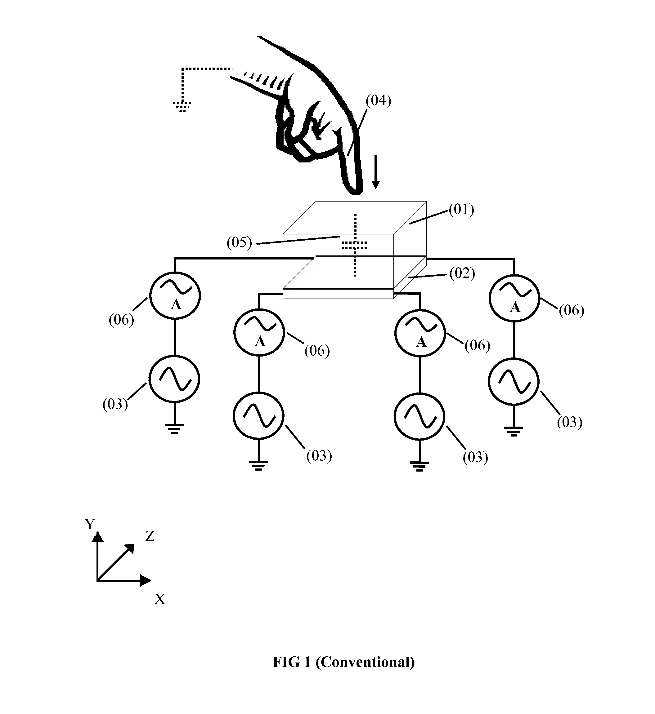
Although simple, surface capacitive type systems are unable to detect multiple simultaneous touch input events as occurs when, for example, two or more fingers are in contact with the touch panel.
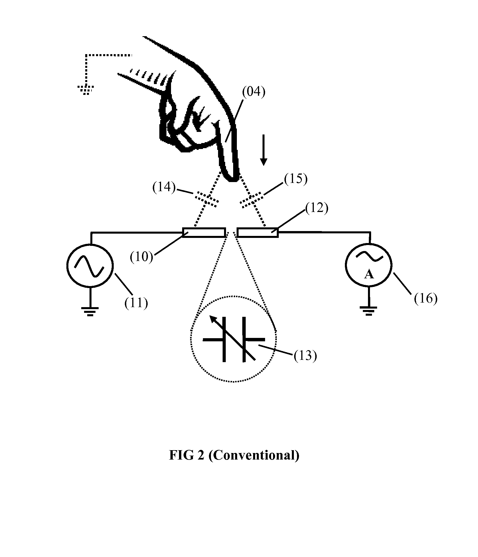
However, in spite of the multi-touch capabilities of the projected capacitive method, it has some significant limitations.
For example, it cannot be used to detect the force of touch input and is unable to detect touch input from non-conductive objects such as a plastic stylus or pen.
A significant limitation of all of the hybrid touch panel devices described above however, is that even though the projected capacitive sensor is capable of determining the location of multiple simultaneous touch input events, the force sensor is incapable of uniquely determining the input force associated with each individual touch input event.
It is therefore impossible to calculate, for example, the force being applied by any one particular input object and the utility of the device is greatly limited.

Method used


Image

  • Dual-function transducer for a touch panel
  • Dual-function transducer for a touch panel
  • Dual-function transducer for a touch panel

Examples


fourth embodiment

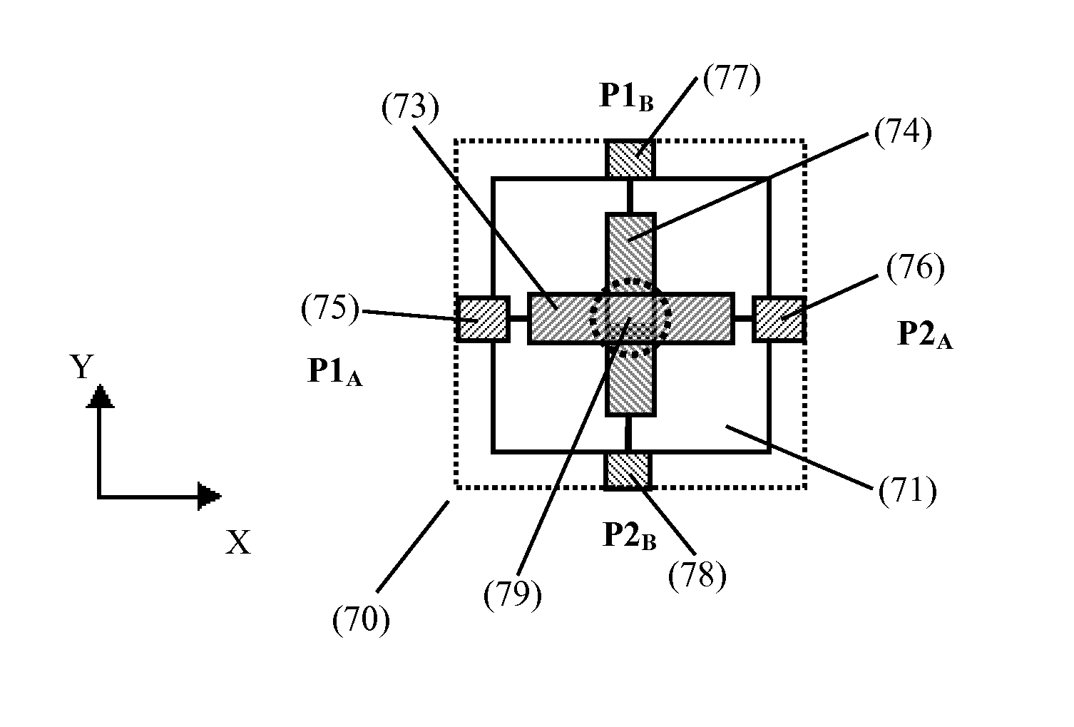
[0217]In a fourth embodiment, the dual-function transducer is formed by a set of row electrodes (FIG. 15A) and a set of column electrodes (FIG. 15B) arranged orthogonally in a matrix. As shown in FIG. 15C, the set of row electrodes (108) is formed on the first surface of the transparent substrate (71) and the set of column electrodes (109) is formed on the second surface of the transparent substrate (71). Each of the row and column electrodes is patterned to form a strain sensor according to the pattern of FIG. 7C. As can be seen in FIG. 15A and FIG. 15B, in the space between each of the row electrodes and column electrodes, a number of dummy features (133), which are preferably made of the same material as the electrodes, can be created to improve the visual appearance of the surface on which the electrodes reside. This arrangement may be considered as a dual-layer structure whereby the set of row electrodes (108) generate signals corresponding to strain induced by compressive forc...

sixth embodiment

[0220]In the present invention, an array of dual-function transducers is built employing a single-layer structure. The structure consists of a substrate (71) and a single-layer transducer arrangement (156) formed on or over the substrate, wherein the single-layer transducer arrangement may be made, for example, of interlocking rhombuses. However, the structure arrangement can be made of any other geometric pattern. The single-layer transducer arrangement (156) further comprises an electrode grid layer (151), an insulating layer (152) formed over the grid layer (151), and a metal bridge layer (153) formed over the insulating layer 152, see cross-sectional view in FIG. 18A. In a preferred configuration of this embodiment, shown in FIG. 18B, a set of row electrodes (108) is formed by individual row electrodes (127) in a transparent conductive material directly on the substrate (71) and patterned to form a set of rhomboidal strain sensors (141) which are connected in series. A set of co...

seventh embodiment

[0221]In the present invention the mechanical layout of the stack is arranged as a dual-layer structure with improved optical uniformity, strain responsivity and noise immunity. In a preferred configuration of this embodiment, shown in FIG. 19, the dual-layer electrode structure consists of a first transparent substrate (71), a set of row electrodes (108) formed by individual row electrodes (127), a bonding electrical insulator (191), a set of column electrodes (109), formed by individual column electrodes (128) and a second transparent substrate (71). The set of row electrodes (108) can be patterned to form a strain sensitive structure as described in previous embodiments, for example, in a rhomboidal pattern. This set of row electrodes (108) is formed on the top surface of the first transparent substrate (71) and forms a first layer (192). The set of column electrodes (74) are patterned to form a strain sensitive structure and are formed on the bottom surface of the second transpa...


PUM


Abstract

A dual-function transducer for a force-sensitive multi-touch screen, including a first substrate, at least one electrode array formed on the first substrate, the at least one electrode array including first and second electrodes, and circuitry operatively coupled to the first and second electrodes. The circuitry is configured to measure first and second electrical properties of the electrode array, the first and second electrical properties corresponding to touch and strain, respectively.

Description

TECHNICAL FIELD[0001]The current invention relates generally to a touch screen and, particularly but not exclusively, to force sensitive multi-touch screens. The invention further relates to a method to generate, scan and process the necessary signals to extract both multi-touch and multi-point force information from touch screens inputs.BACKGROUND ART[0002]Touch panels have recently become widely adopted as the input device for high-end portable electronic products such as smart-phones and tablet devices. Although, a number of different technologies can be used to create these touch panels, capacitive systems have proven to be the most popular due to their accuracy, durability and ability to detect touch input events with little or no activation force.[0003]The most basic method of capacitive sensing for touch panels is demonstrated in surface capacitive systems as illustrated in FIG. 1. Surface capacitive systems, for example as disclosed in U.S. Pat. No. 4,293,734 (Pepper, Oct. 6...

Claims


Application Information

Patent Timeline
Patent Type & Authority Patents(United States)
IPC IPC(8): G06F3/044G06F3/041
CPCG06F3/044G06F3/0414G06F2203/04106G06F3/0443G06F3/0447
Inventor CASTILLO, SERGIO G.BROWN, CHRISTOPHER J.
Owner SHARP KK
Learn More