Connecting apparatus for connection of field devices

a technology of connecting apparatus and field device, which is applied in the direction of emergency power supply arrangement, program control, nuclear elements, etc., can solve the problems of voltage drop, interference with telegrams, failure of respective field devices,

Active Publication Date: 2014-07-22
SIEMENS AG
View PDF10 Cites 2 Cited by
  • Summary
  • Abstract
  • Description
  • Claims
  • Application Information

AI Technical Summary

Benefits of technology

[0009]The connecting apparatus has a measurement device, which is arranged between the coupling units and the field device connection to eliminate a disturbance signal over the signal path, where the measurement device is configured to detect a current change and to operate a switching element such that a current flow through the field device connection is interrupted. The described current change can occur, for example, as follows: during a starting-up phase of an automation system having a fieldbus, connecting apparatuses and field devices, or during a further extension of the fieldbus, it is possible for a fitter to wish to connect a field device to an existing connecting apparatus by contacts that are provided to the connecting apparatus. The connection process is a manual activity and not a clean, exact or precise switching process. As a result, it is possible for the line with its conductors to briefly make contact, and to break contact again because of the mechanical introduction, thus causing disturbances when the line is connected to the field device and the field device is, in turn, intended to be connected to contacts of the connecting apparatus. However, the connecting apparatus in accordance with the invention has the distinct advantage in that an initial contact with the conductors of the line is identified at the contacts because a first current flows, although for a short time. The measurement device identifies this current value, where the measurement device subsequently signals this identified current change to a switching element that immediately interrupts the current flow through the field device connection. As a result, the disturbances can no longer cause any noticeable reaction on the bus.
[0011]In another embodiment, the connection apparatus has a current rise limiting circuit in the power supply path to furthermore minimize the disturbances and reactions on the bus caused by a connection process. Here, the current rise limiting circuit also represents a form of decoupling, because the current rise limiting circuit allows only a slow current change, such that the disturbing current changes, which themselves are rapid, cannot be made noticeable on the bus.

Problems solved by technology

The voltage dip caused by the connection process could, for example, result in other connected field devices being reset, leading to a failure of the respective field devices and / or to collapse of the entire communication process.
This bouncing would cause voltage drops during telegram transmission, and would interfere with the telegrams.
The connection process is a manual activity and not a clean, exact or precise switching process.
As a result, it is possible for the line with its conductors to briefly make contact, and to break contact again because of the mechanical introduction, thus causing disturbances when the line is connected to the field device and the field device is, in turn, intended to be connected to contacts of the connecting apparatus.
For example, the time period could be set to 5 seconds because, after an initial contact, which leads to a current change or to a current surge, it can be said with sufficient probability after 5 seconds has elapsed that the conductors of the line to the field device have now been securely mounted on the contacts of the connecting apparatus and, as a consequence, it is no longer possible for any disturbing current changes to occur.

Method used


Image

  • Connecting apparatus for connection of field devices
  • Connecting apparatus for connection of field devices

Examples


Embodiment Construction

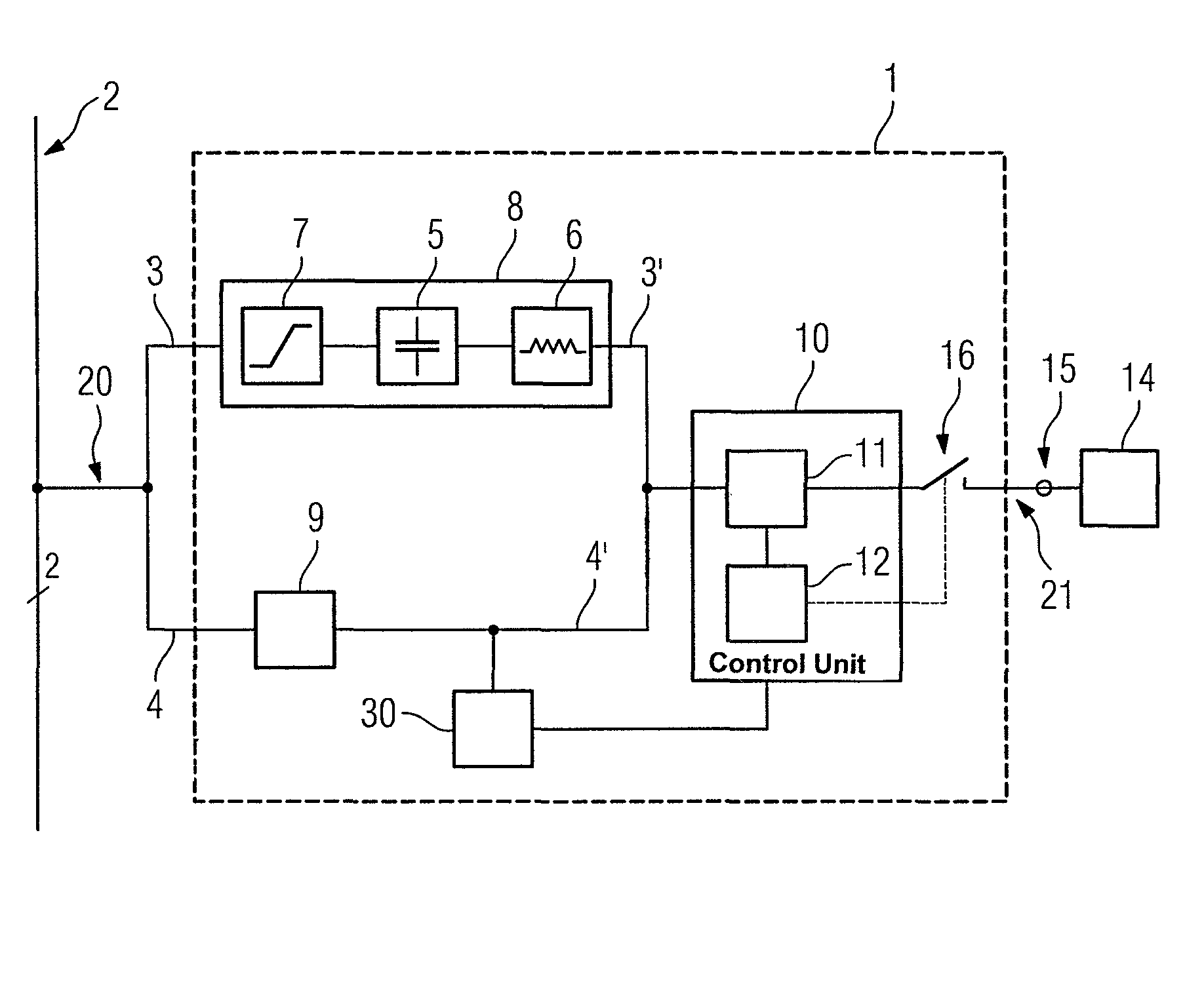
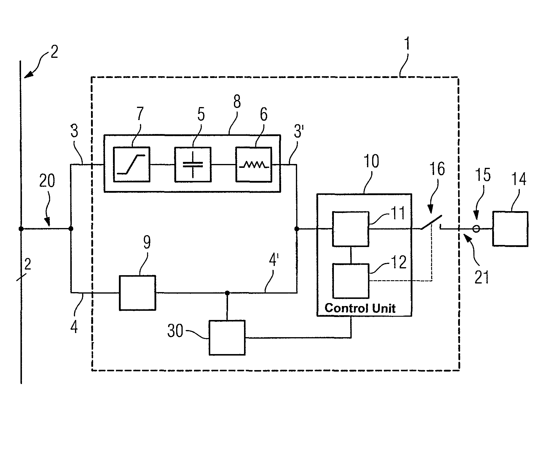
[0019]The FIGURE illustrates a connecting apparatus 1 for field devices 14. The connecting apparatus 1 has a bus connection 20 that is connected to a bus 2. The bus 2 comprises a two-wire Profibus PA. The connecting apparatus 1 also has a field device connection 21 to connect field devices 14. The connecting apparatus 1 furthermore has contacts 15 to allow the field devices 14 to be connected to the connecting apparatus 1 via appropriate lines with their conductors.

[0020]A power supply path 3, 3′ for transmitting a supply voltage which is provided in addition to a data signal through the bus 2, and a signal path 4, 4′ for the data signal, are arranged between the bus connection 20 and the field device connection 21. Here, the power supply path 3, 3′ and the signal path 4, 4′ are arranged in parallel with one another between the bus connection 20 and the field device connection 21. This arrangement allows the supply voltage and the data signal that are both present on the bus 2 to be...


PUM


Abstract

A connecting apparatus for connection of field devices comprising a bus connection for connection to a bus, a field device connection for connection for a field device, a power supply path and a signal path, wherein the power supply path and the signal path are arranged in parallel with one another between the bus connection and the field device connection such that a supply voltage carried on the bus is isolated from a signal, which is likewise carried on the bus, by a first coupling unit arranged in the power supply path and a second coupling unit arranged in the signal path.

Description

BACKGROUND OF THE INVENTION[0001]1. Field of the Invention[0002]The invention relates to connection devices and, more particularly, to a connecting apparatus for interconnecting field devices, comprising a bus connection for connection to a bus and a field device connection for connection of a field device.[0003]2. Description of the Related Art[0004]WO 2005 / 053221 A2 discloses connecting apparatuses. Reference is expressly made to WO 2005 / 053221 A2 with regard to the capability to implement the present invention with respect to the connecting apparatus for field devices during operation of a network, such as a Profibus PA network. Accordingly, the content of WO 2005 / 053221 A2 is incorporated herein by reference in its entirety.[0005]In the case of connecting apparatuses for field devices that communicate over a bus, i.e., a fieldbus, with a superordinate automation appliance, the bus cable forms a common component for all the field devices. Consequently, the failure of the bus cabl...

Claims


Application Information

Patent Timeline
Patent Type & Authority Patents(United States)
IPC IPC(8): G05B19/042H02J1/00
CPCG05B19/0425Y10T307/549Y10T307/707Y10T307/685Y10T307/615
Inventor VOLKMANN, HANS
Owner SIEMENS AG
Why Eureka
Try Eureka