Image forming apparatus with structure for suppressing position variation of exposure unit caused by vibrations generated therein

a light scanning and exposure unit technology, applied in the direction of instruments, printing, measurement devices, etc., can solve the problems of insufficient positioning in the direction of gravity, defective image, and difficulty in ensuring the scanning position of laser beams on the surface of photosensitive drums, so as to reduce the vibration transmitted from the placement unit to the light scanning apparatus.

Inactive Publication Date: 2014-07-22
CANON KK
View PDF6 Cites 1 Cited by
  • Summary
  • Abstract
  • Description
  • Claims
  • Application Information

AI Technical Summary

Benefits of technology

[0008]The present invention has been made in view of the above-mentioned circumstances, and it is an object of the present invention to reduce a vibration transmitted from a placement unit to a light scanning apparatus and to determine a position of the light scanning apparatus on the placement unit.
[0010]According to the present invention, a vibration transmitted from the placement unit to the light scanning apparatus can be reduced and the position of the light scanning apparatus on the placement unit can be determined.

Problems solved by technology

This leads to a change in a laser irradiation position of a laser light emitted from the light scanning apparatus to the photosensitive drum, causing a defective image.
However, positioning in the direction of gravity may not be achieved to a sufficient level.
As a result, it may be difficult to guarantee a laser beam scanning position on a surface of a photosensitive drum.
In addition, in the image forming apparatus disclosed in Japanese Patent Application Laid-Open No. 2004-98441, although positioning in the direction of gravity can be achieved by adjusting a tightening amount of the adjustment screw, the laser scanner and the scanner supporting component are integrated by the adjustment screw and thus vibrate together, weakening the anti-vibration effect obtained by interposing the anti-vibration member between the laser scanner and the scanner supporting component.
Further, although the anti-vibration member is interposed between the laser scanner and the scanner supporting component, there is a possibility that the adjustment screw becomes another path for transmitting the vibration, and the vibration is transmitted from the scanner supporting component to the laser scanner.

Method used


Image

  • Image forming apparatus with structure for suppressing position variation of exposure unit caused by vibrations generated therein
  • Image forming apparatus with structure for suppressing position variation of exposure unit caused by vibrations generated therein
  • Image forming apparatus with structure for suppressing position variation of exposure unit caused by vibrations generated therein

Examples


first embodiment

[0022

[0023]Outline of Image Forming Apparatus

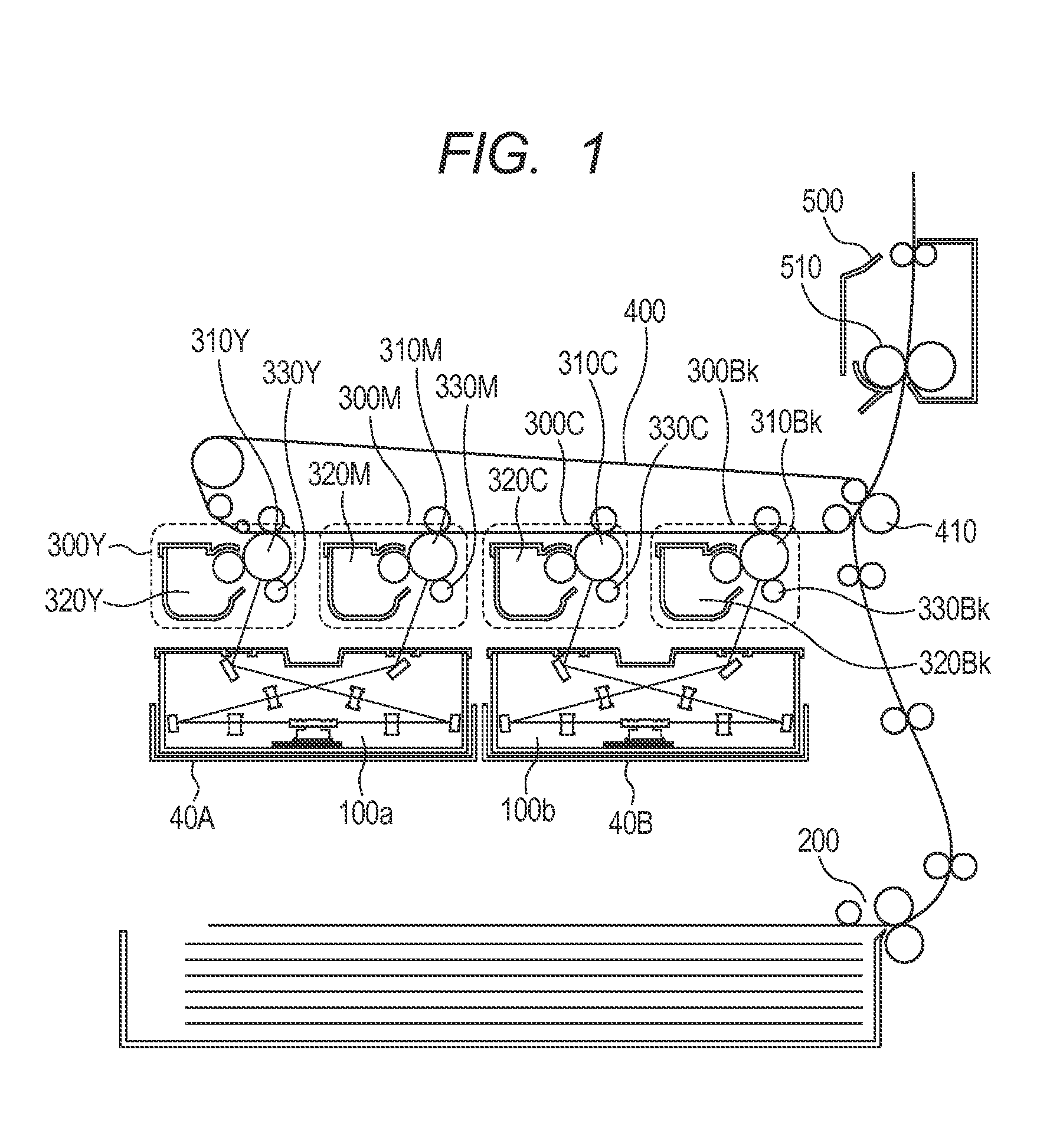
[0024]FIG. 1 is a schematic diagram illustrating a configuration of an image forming apparatus according to a first embodiment. The image forming apparatus illustrated in FIG. 1 includes four image forming engines 300Y, 300M, 300C, and 300Bk configured to respectively form toner images of yellow, magenta, cyan, and black. Hereinafter, the symbols Y, M, C, and Bk are omitted except when a specific color is described. The image forming engine 300 includes a photosensitive drum 310, a charging roller 330, and a developing device 320. The charging roller 330 charges the photosensitive drum 310 to a uniform potential, and the developing device 320 develops an electrostatic latent image formed on the photosensitive drum (image bearing member) 310 by an exposure with laser light output from a light scanning apparatus (latent image forming unit) 100 into a toner image. The image forming engine 300 forms the toner image corresponding to image data...

second embodiment

[0048

[0049]Configuration of Light Scanning Apparatus Mounting Portion

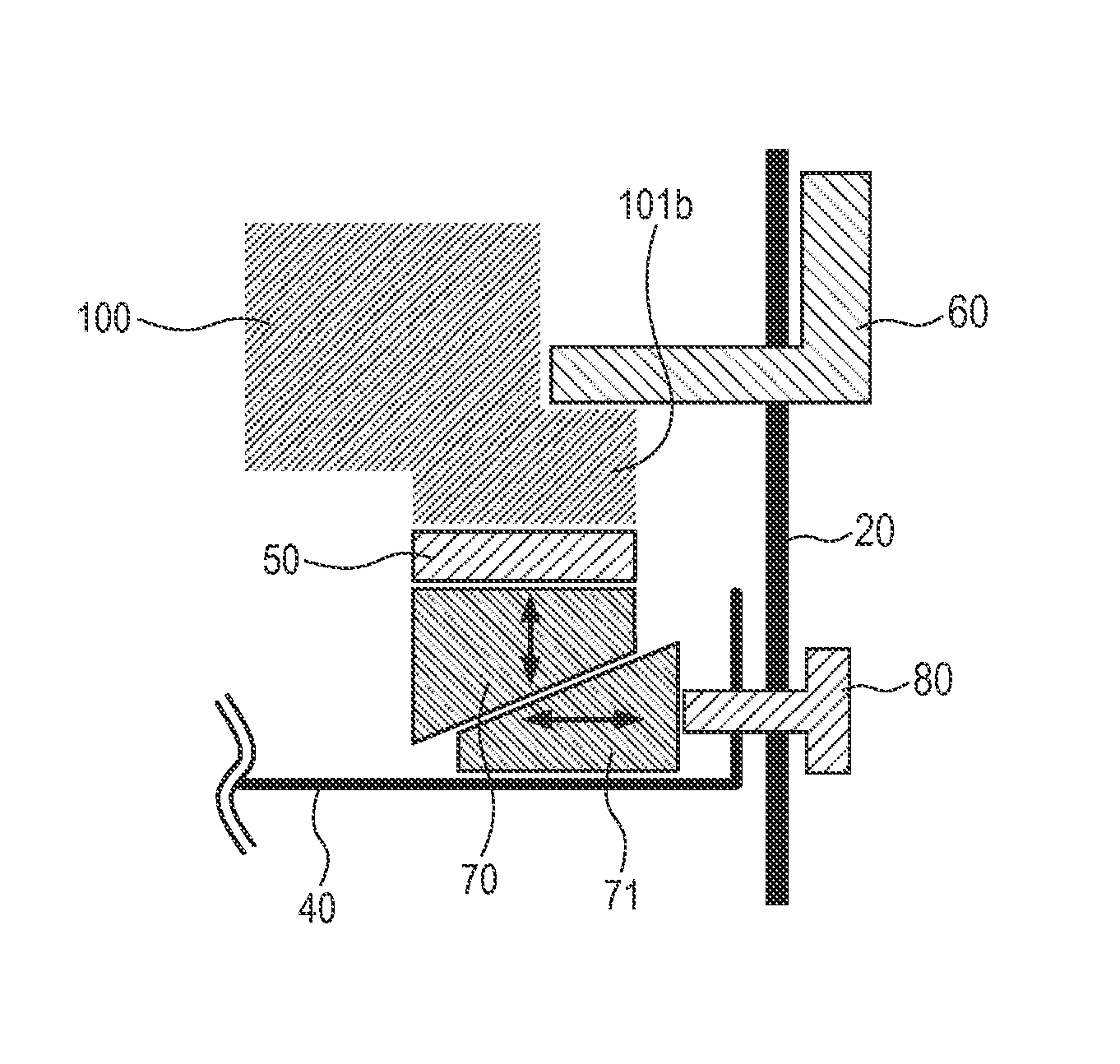
[0050]An image forming apparatus according to a second embodiment of the present invention has basically the same configuration as the configuration described in the first embodiment, except that a difference exists in the connecting portion of the stay 40 and the light scanning apparatus 100. FIGS. 1 to 5 described in the first embodiment are incorporated in the second embodiment. FIG. 8 is a diagram illustrating the connecting portion of the stay 40 and the light scanning apparatus 100 according to the second embodiment, including, unlike the image forming apparatus according to the first embodiment, a mechanism configured to adjust the compression amounts of the elastic members 50.

[0051]Adjustment of Compression Amount of Elastic Member

[0052]In order to adjust the compression amount of the elastic member 50, cams 70 and 71 (adjustment unit) are provided between the elastic member 50 and the stay 40. The cam 70 i...


PUM


Abstract

An image forming apparatus, including: an image bearing member; a latent image forming unit configured to emit a light beam based on image data and to form an electrostatic latent image on the image bearing member by the light beam; a placement unit provided in a main body of the image forming apparatus, on which the latent image forming unit is placed; an elastic member disposed between the latent image forming unit and the placement unit; and a pressing unit provided in the main body of the image forming apparatus and configured to press the latent image forming unit toward the placement unit so that the elastic member is pressed by the latent image forming unit and the placement unit.

Description

BACKGROUND OF THE INVENTION[0001]1. Field of the Invention[0002]The present invention relates to vibration and positioning of a light scanning apparatus in an image forming apparatus.[0003]2. Description of the Related Art[0004]In general, each component such as a light scanning apparatus, a photosensitive drum, a developing device, or a fixing device in an image forming apparatus is mounted on a support member such as a stay, and is mounted, together with the support member, on two side plates provided in the image forming apparatus in a state of being mounted on the support member. In such a configuration, a vibration generated by motor driving or engagements of gears of the photosensitive drum, the developing device, or the fixing device is transmitted through the side plates and the stay, finally to the light scanning apparatus. As a result, the light scanning apparatus itself or an optical component provided in the light scanning apparatus is forcedly vibrated. If the frequency...

Claims


Application Information

Patent Timeline
Patent Type & Authority Patents(United States)
IPC IPC(8): B41J2/435B41J15/14B41J27/00
CPCB41J2/471G03G21/1666G03G2221/1654
Inventor ARUGA, DAISUKE
Owner CANON KK
Why Eureka
Try Eureka