Surgical microscope system

Inactive Publication Date: 2014-07-22
MITAKA KOHKI
View PDF25 Cites 30 Cited by
  • Summary
  • Abstract
  • Description
  • Claims
  • Application Information

AI Technical Summary

Benefits of technology

[0006]It is an object of the present invention, which has been conceived to solve the above problems, to provide a surgical microscope system which allows an assistant operator to observe the operation site in a magnified manner within his / her own visual field from a position in alignment with, or from a position opposite to, or at a right-front or left-front position of the principal operator.
[0009]In addition, the horizontal axis is not necessarily required to be strictly “horizontal”, but should be understood that it is sufficiently horizontal to an extent such that the principal operator or the assistant operator can look into the display device without difficulty after having rotated the display device.
[0024]According to the present invention, a surgical microscope system is provided which allows an assistant operator to observe the operation site in a magnified manner within his / her own visual field from a position in alignment with, or opposite to, or the right-front or left-front of, the principal operator.

Problems solved by technology

However, “facing” in this case does not necessarily mean that the angle between the principal operator and the assistant operator is strictly 180° across the operation site, but may be slightly off 180°, provided that the assistant operator can properly assist the surgery.

Method used


Image

  • Surgical microscope system
  • Surgical microscope system
  • Surgical microscope system

Examples


first embodiment

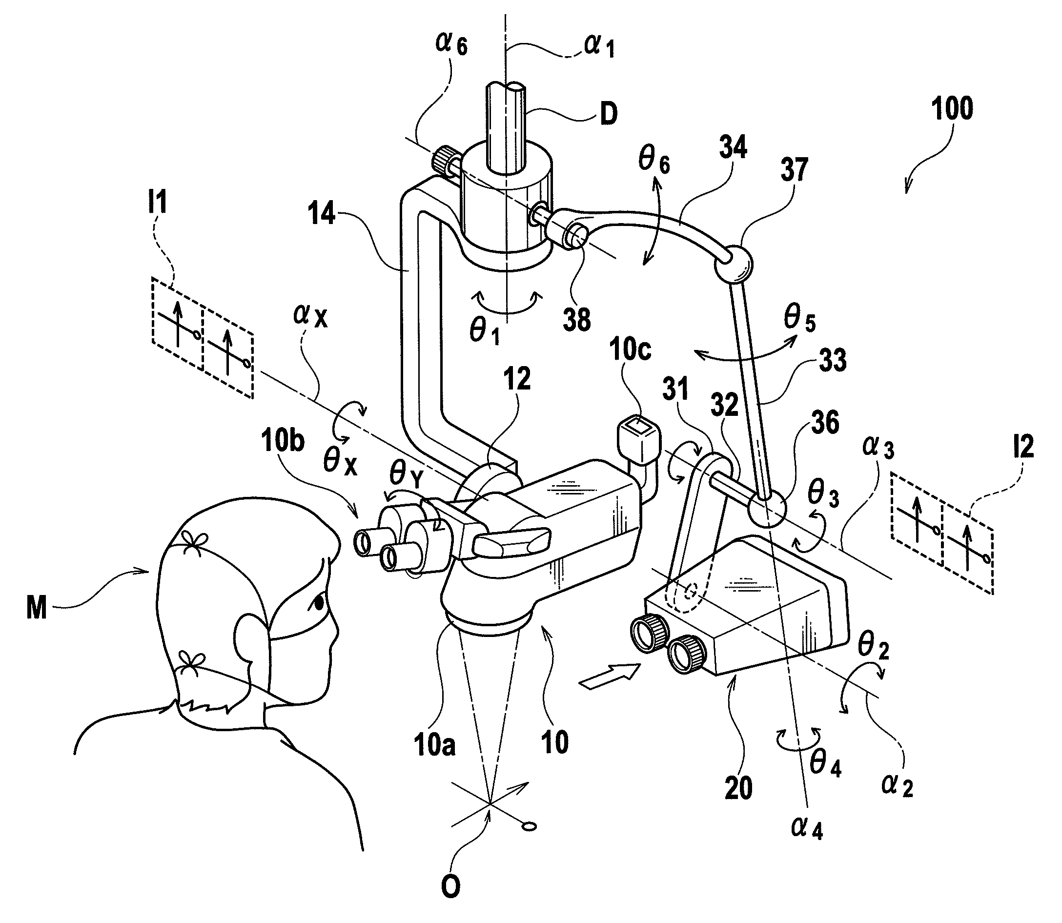
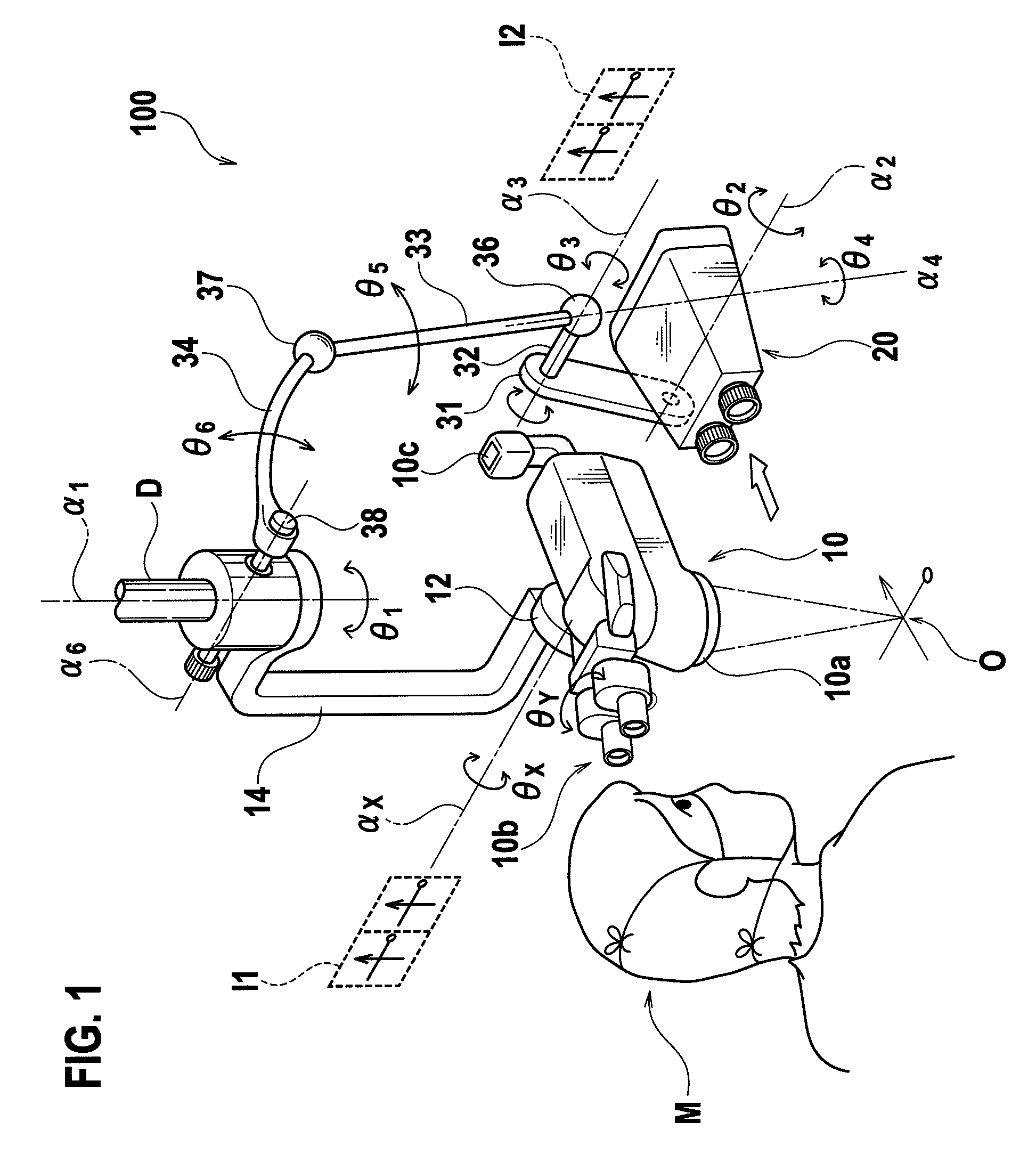
[0041]Referring to FIG. 1, the surgical microscope system 100 comprises a medical optical instrument stand (not shown), a main microscope 10 attached to a tip arm D of the medical optical instrument stand via a predefined arm (described below), and a stereo viewer 20.

[0042]The main microscope 10 is mainly used by the principal operator M (surgeon) to magnify the operation site O for observation. As shown, the main microscope 10 is attached to one end of an arm 14 via an electro-magnetic clutch 12. As well as allowing the main microscope 10 to rotate in the θX direction about the axis αX, the electro-magnetic clutch 12 can fix the main microscope 10 at a predefined angle. The other end of the arm 14 is attached to the tip arm D of the medical optical instrument stand. The arm 14 is rotatable in the θ1 direction about the central axis α1 of the tip arm D. In addition, the main microscope 10 is also rotatable in the θY direction by an electro-magnetic clutch which is not shown.
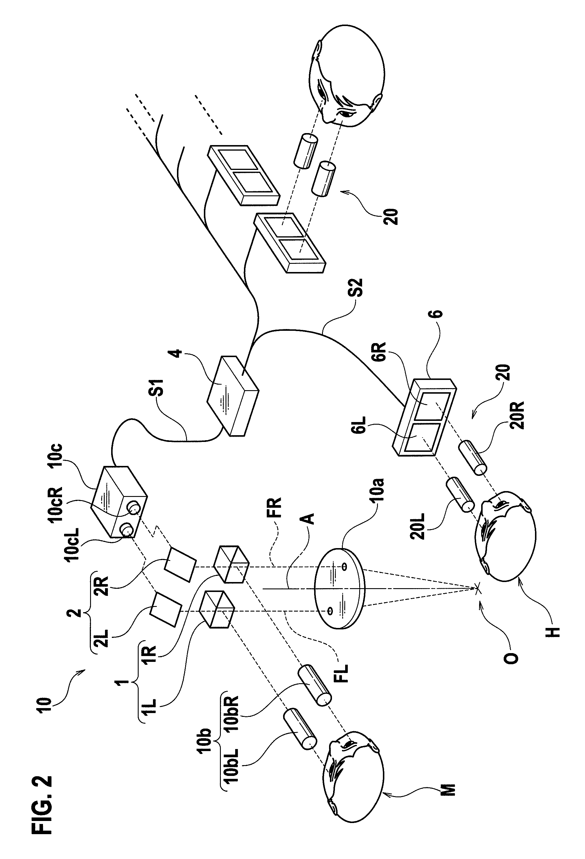
[0043]On...

second embodiment

[0064]FIG. 5 is a schematic view illustrating a surgical microscope system according to a second embodiment. As shown, the surgical microscope system 200 comprises a main microscope 11 and a stereo viewer 21. The main microscope 11 is movably attached to the tip arm D of the medical optical instrument stand by a predefined arm, similarly with the main microscope 10 in the first embodiment. The main microscope 11 has an arrangement identical to that of the main microscope 10 in the first embodiment except that its internal optical structure is different, and it has an additional television camera 11c.

[0065]In addition, the stereo viewer 21 is movably attached to the tip arm D of the medical optical instrument stand by the support member including the arms 31 to 34, similarly with the stereo viewer 20 in the first embodiment. However, in the second embodiment, the stereo viewer 21 is disposed so that the assistant operator H using it can stand at the right front of the principal oper...

third embodiment

[0080]A surgical microscope system according to a third embodiment is identical to the surgical microscope system 200 of the second embodiment in terms of arrangement. However, the surgical microscope system according to the third embodiment differs from the surgical microscope system 200 in that the stereo viewer 21 is disposed so that the assistant operator H using the stereo viewer 21 can be positioned at the left-front of the principal operator M using the main microscope 11 and can face the operation site O from there.

[0081]Such an arrangement is realized by moving the stereo viewer 21 in the following manner, using the support member including the arms 31 to 34, the stereo viewer 21 being disposed at the right-front seen from the principal operator M using the main microscope 11 in the surgical microscope system 200.

[0082]Referring to FIG. 11, in the surgical microscope system 300 according to the third embodiment, the stereo viewer 21 is rotated about the axis α1 horizontally...


PUM


Abstract

The surgical microscope system includes a first binocular microscope and a first display device. The first binocular microscope includes an objective lens, a first right ocular lens which provides a first image based on a light flux transmitted through the objective lens, and a first left ocular lens which provides a second image based on a light flux transmitted through the objective lens. The first display device can be disposed opposite to or in alignment with the first binocular microscope, and includes a first right-eye image display surface for displaying the first image and a first left-eye image display surface for displaying the second image. The first display device can be reversed about a horizontal axis extending in a direction along which the first right-eye image display surface and the first left-eye image display surface are located in alignment.

Description

TECHNICAL FIELD[0001]The present invention relates to a surgical microscope system which provides magnified images of the operation site, and particularly to a surgical microscope system which can provide magnified images to the principal operator and an assistant operator of the surgery.BACKGROUND ART[0002]In recent years, along with development of medical technology, microsurgery using a surgical microscope has been widely performed. In microsurgery, there may be a case where an assistant operator who assists the principal operator is needed in addition to the principal operator (surgeon), particularly for a complex surgery. In this case, not only the principal operator but also the assistant operator may need to observe the operation site in a magnified manner, for which a surgical microscope has been developed as disclosed in Japanese Unexamined Patent No. 2005-137932 wherein a microscope is also disposed for use by the assistant operator in addition to the microscope for use by...

Claims


Application Information

Patent Timeline
Patent Type & Authority Patents(United States)
IPC IPC(8): G02B21/00G02B21/22G02B21/36
CPCG02B21/22G02B21/361G02B21/0012A61B19/26A61B19/5223A61B90/50A61B90/20
Inventor NAKAMURA, KATSUSHIGE
Owner MITAKA KOHKI
Why Eureka
Try Eureka