Unlock instant, AI-driven research and patent intelligence for your innovation.

Transmission system

a transmission system and transmission line technology, applied in the field of transmission systems, can solve the problems of not finding a technique to apply to the 1:1 protection scheme, packet loss caused by switching lines, and packet loss caused by packet loss

Active Publication Date: 2014-07-22
NEC CORP
View PDF10 Cites 0 Cited by
  • Summary
  • Abstract
  • Description
  • Claims
  • Application Information

AI Technical Summary

Benefits of technology

The present invention allows for line switching for preventive maintenance without causing any loss of packets or changes in their sequence. This is possible because it compensates for errors in received frames using error correction. The switching can be done during the time when error correction is being compensated, which ensures that no frame loss will be caused by an error. This results in a hitless switching process.

Problems solved by technology

In the 1:1 protection standardized by the ITU-T, if the switching target line is a high-speed line having a smaller delay quantity compared with that of the switching source line, there is a problem that a packet loss is caused when switching lines.
As such, there is a problem that the sequence of the packets will be changed.
Further, although switching lines for preventive maintenance based on the status of error correction of the received frames is performed in the 1+1 protection scheme as described in Patent Document 2, a case of applying such a technique to the 1:1 protection scheme has not been found.
The grounds are as follows: as the status of error correction of the received frames is only detected by the reception side, it is considered difficult to apply the technique to the 1:1 protection in which path switching is performed at the transmission side; and as a packet loss or a change in the sequence of packets is caused if there is any delay difference between the two lines in the 1:1 protection as described above, preventive maintenance cannot be realized.

Method used


Image

  • Transmission system
  • Transmission system
  • Transmission system

Examples


first exemplary embodiment

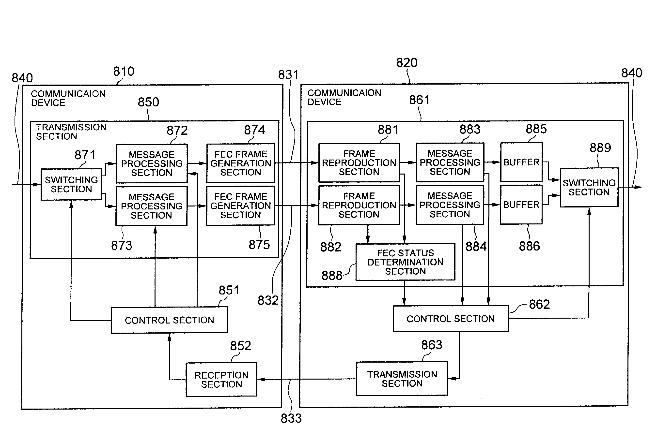
[0037]Referring to FIG. 8, a transmission system according to a first exemplary embodiment of the present invention is configured such that a communication device 810 and a communication device 820 are connected with each other via a line 831 and a line 832 to be used for transmission from the communication device 810 to the communication device 820, and via a line 833 to be used for transmission from the communication device 820 to the communication device 810.

[0038]The communication device 810 has a function of, when receiving a predetermined message from the line 833 in a state of transmitting the frames of traffic 840 such as user traffic to the line 831 while performing error-correction coding on the frames, switching the line used for transmission from the line 831 to the line 832, and then transmitting a frame of a post-switching message to the line 831.

[0039]The communication device 820 has a function of receiving the frames from the line 831 and the line 832 and performing ...

second exemplary embodiment

(Description of Configuration)

[0052]Referring to FIG. 1, a transmission system according to a second exemplary embodiment of the present invention includes transmission / reception devices 104 and 105, and four lines 200, 201, 202, and 203 connecting the devices 104 and 105.

[0053]Each of the line 200 and the line 201 may be formed of one communication line or one transmission path, or formed of a plurality of communication lines or transmission paths connected via relay devices. Further, in the line 200 and the line 201, a delay time of a packet transmitted from the transmission / reception device 104 until it reaches the transmission / reception device 105 may be almost the same or different.

[0054]Each of the line 202 and the line 203 may be formed of one communication line or one transmission path, or formed of a plurality of communication lines or transmission paths connected via relay devices. Further, in the line 202 and the line 203, a delay time of a packet transmitted from the tra...

third exemplary embodiment

[0129]While the second exemplary embodiment described above is configured such that the lines in both directions are switched simultaneously triggered by deterioration in the line state of one or both of the switching source lines 200 and 202, in the present embodiment, line switching is performed in a single direction. Specifically, in FIG. 1, after the FEC status determination section 106 of the transmission / reception device 105 receives a switching request signal (step S14 in FIG. 3), the control section 18 transmits a switching notification message transmission command signal to the message processing section 20. In accordance with the switching notification message transmission command signal from the control section 18, the message processing section 20 combines a switching notification message using VSM of the Ethernet OAM with the user traffic, and transmits the result to the transmission / reception device 104 via the switching source line 202. The message processing section ...


PUM


Abstract

When a first communication device receives a predetermined message from a second communication device via a third line (L3) in a state of transmitting frames to a first line (L1) while performing error-correction coding on the frames, the first communication device switches the line used for transmission from L1 to the second line (L2), then transmits a frame of a post-switching message to L1 . The second communication device receives frames from L1 and L2 and performs error correction, stores the frames, on which error correction has been performed, in first and second buffers (B1, B2), and when determining that it is necessary to perform line switching based on the status of error correction with respect to the frames received from L1, transmits a predetermined message to L3, and when receiving the frame of the post-switching message from L1, starts reading frames from B2 after reading all frames stored in B1.

Description

TECHNICAL FIELD[0001]The present invention relates to a transmission system in which communication devices are connected via a plurality of lines in order to improve the reliability of communication, and in particular, to a technique of switching lines to be used for communication.BACKGROUND ART[0002]A 1:1 protection scheme is standardized by ITU-T (International Telecommunication Union) (ITU-T Recommendation G8031). In this scheme, a transmission device and a reception device are connected via two lines in order to improve the reliability of communication, and in the initial state, communication is performed using one of the lines, while at the time of maintenance work or failure, communication is performed using the other line. In particular, in the 1:1 protection standardized by the ITU-T, a line can be switched to another line by the unit of VLAN traffic based on a switching request by a user.[0003]In the 1:1 protection standardized by the ITU-T Recommendation G8031, the line sw...

Claims


Application Information

Patent Timeline
Patent Type & Authority Patents(United States)
IPC IPC(8): H03M13/00H04L69/14H04L69/40
CPCH04L1/22H04L1/0045H04L1/203H04L29/04H04L49/557H04L69/14H04L69/40
Inventor KATAOKA, HIROAKIKAMADA, SHINYA
Owner NEC CORP