
Footwear and related method of manufacture

a manufacturing method and technology for footwear, applied in the field of footwear, can solve the problems of affecting the manufacture and assembly of footwear for centuries, requiring substantial labor input on multiple levels, and assembling footwear is a labor intensive process, so as to achieve the effect of saving significant assembly and processing time and labor costs, facilitating sealing footwear, and reducing pattern retooling costs and tim

Active Publication Date: 2014-07-29
WOLVERINE OUTDOORS
View PDF44 Cites 37 Cited by
  • Summary
  • Abstract
  • Description
  • Claims
  • Application Information

AI Technical Summary

Benefits of technology

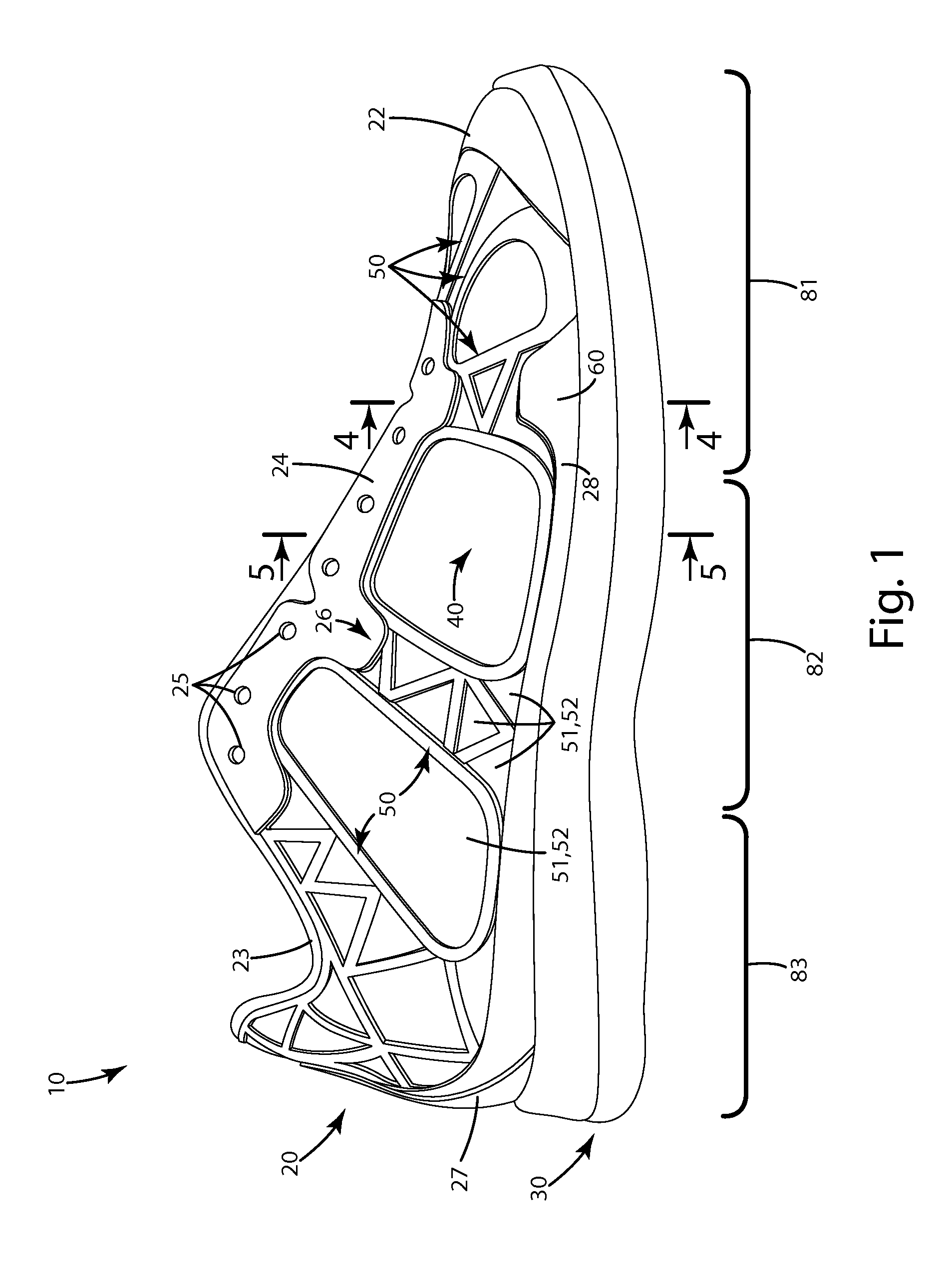
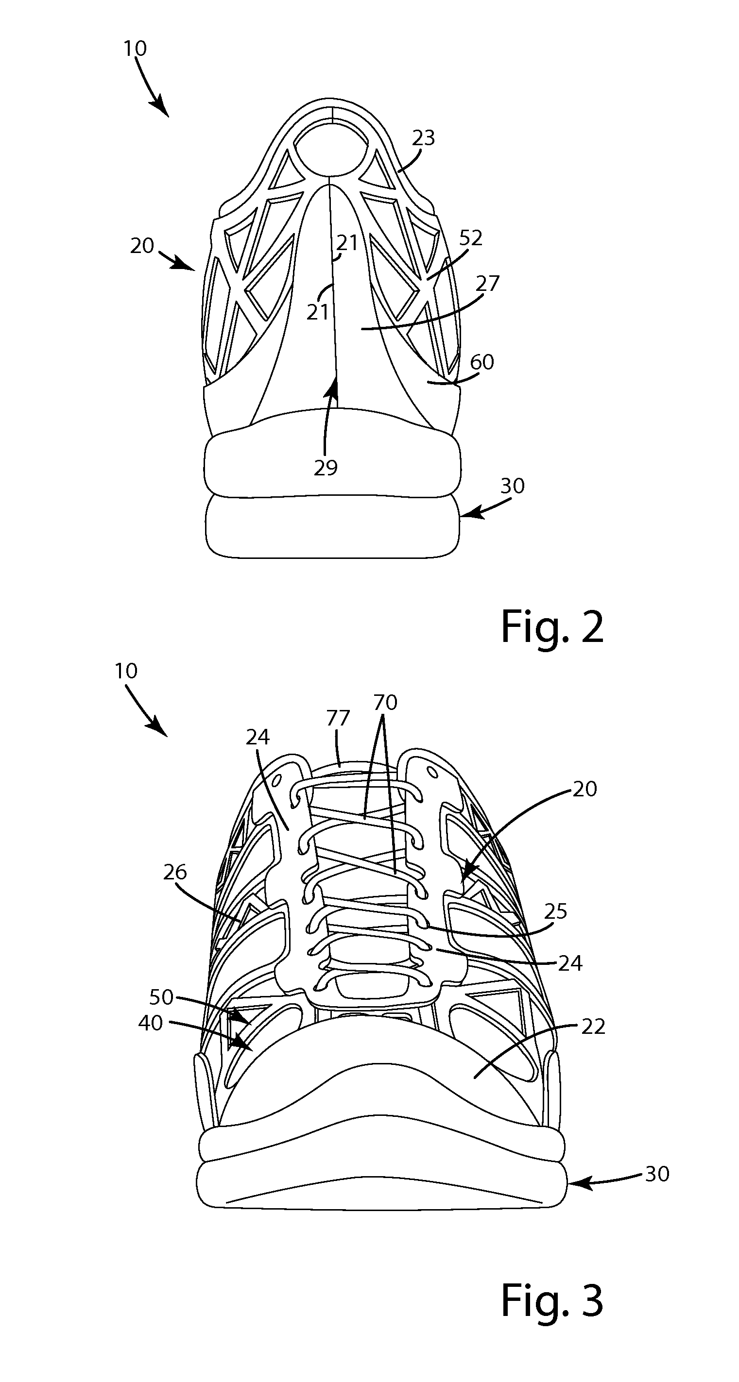
The patent text describes a method of making footwear by using an exoskeleton that is molded onto a base sheet and then raised above the surface of the sheet. This exoskeleton can be formed to provide specific structural components of the footwear, such as a toe box or an ankle collar. The method is labor- and time-saving, allowing for the elimination of multiple steps and reducing costs. It also allows for the introduction of a single seam design, making it easier to seal the footwear. The method can be implemented in small, micro-manufacturing facilities, making it suitable for high-volume production.

Problems solved by technology

A problem that has plagued the manufacture and assembly of footwear for centuries, however, still remains.
The problem is that making and assembling footwear is a labor intensive process.
Footwear typically requires substantial labor input on multiple levels.
All of the foregoing steps require substantial labor input.
Moreover, the amount of labor required is compounded by the fact that every time a new footwear design, style, or size is desired, the manufacturing method must be retooled to accommodate the variations.
Unfortunately, while many have tried to address the labor intensity issues concerning footwear, they remain as much a problem now as they did at the turn of the century.
The issue with the foregoing construction, however, is that if the material used to construct the upper is not rigid enough it typically lacks structural integrity, and a wearer will feel like they do not have enough support.
On the other hand, if the material used to make the upper is too rigid, it is inflexible, and can potentially harm the wearer's foot.
Further, because the components are only embossed or painted on the footwear, upon closer inspection, the resultant product can suffer aesthetically.

Method used


Image

  • Footwear and related method of manufacture
  • Footwear and related method of manufacture
  • Footwear and related method of manufacture

Examples


first alternative embodiment

IV. First Alternative Embodiment

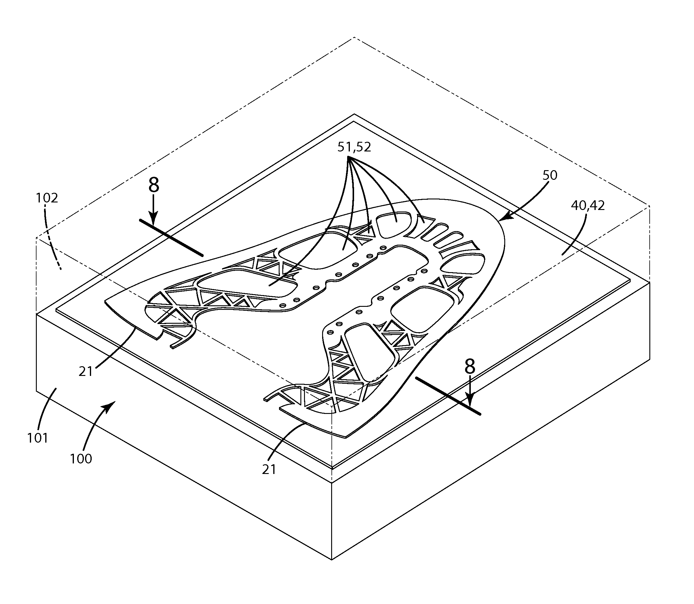
[0082]A first alternative embodiment of the footwear and related method of manufacture is illustrated in FIG. 13. This embodiment relates primarily to the construction of the exoskeleton and is similar to the embodiment described above with several exceptions. For example, the exoskeleton 150 is joined with the base material 40 / sheet 42 in such a manner that the heel element 123 is completely surrounded by the exoskeleton 150. In contrast, the exoskeleton adjacent the toe box 122 defines a gap 122 that separates the marginal ends 121 of the exoskeleton 150 in a region corresponding to a toe box. With this construction, the seam that closes the finished upper, after the base material 140 / sheet 142 and exoskeleton 150 are placed on the last, is located within the toe box 122 of the finished construction. Accordingly, this type of footwear differs from the current embodiment above in that the seam that substantially closes the upper is at the front of th...

second alternative embodiment

V. Second Alternative Embodiment

[0084]A second alternative embodiment of a method of manufacturing the footwear is illustrated in FIG. 14. The footwear and method of this embodiment are similar to the above embodiments with several exceptions. For example, when the exoskeleton 250 is molded, multiple dowel holes 258 are formed along a lower peripheral allowance 229 of the exoskeleton 250, or upper in general. When the exoskeleton 250 and the base material 240 / sheet 242 are placed on the last 109 as shown in FIG. 15, the lower portion of the exoskeleton can be held in place by dowels 211 associated with the last 109 where the dowels project at least partially into and / or through the holes 258. In this manner, the exoskeleton 250 and base material 240 / sheet 242 and more generally the three-dimensional upper 220, can be held in a fixed position relative to the last. While in this fixed position, an outsole mold 207 can be brought into proximity to the last 209 to mold a sole component,...

third alternative embodiment

VI. Third Alternative Embodiment

[0085]A third alternative embodiment of a method of manufacturing the footwear is illustrated in FIG. 16. The footwear and method of this embodiment are similar to the above embodiments with several exceptions. For example, the exoskeleton 350 can be molded to the sheet 342 while the sheet is contoured and / or conformed to a three-dimensional form on a last 309.

[0086]In general, a flat sheet 342 of base material 340, such as that described in the embodiments above, is provided. The flat sheet 342 is reconfigured and conformed to the three-dimensional contours of the last 309. A mold 307 is placed adjacent the three-dimensional contours of the last, with the base material 340 / base sheet 342 located between the last and the mold. The mold 307 defines mold cavities 350C that correspond to the locations in which the exoskeleton 350 is desired to be formed on the base material 340 / base sheet 342. A polymeric material 350A is injected at a molding pressure i...


PUM

PropertyMeasurementUnit
areaaaaaaaaaaa
areaaaaaaaaaaa
areaaaaaaaaaaa

Abstract

A method for manufacturing footwear including injection molding a polymeric material on a sheet of material in preselected locations and / or in a preselected pattern so that the polymeric material bonds to the sheet and forms a structural exoskeleton of an upper of the footwear. The upper can be joined with a sole. The polymeric material can be injection molded on the sheet while the sheet is in a planar or flat configuration, and subsequently, the sheet and bonded exoskeleton can be conformed to a three-dimensional configuration of an upper. Additional polymeric materials can be injected on the exoskeleton to reinforce certain areas of the same. The exoskeleton can define one or more holes through which the sheet is visible to form one or more aesthetic regions on the upper. An article of footwear constructed with the method is also provided.

Description

BACKGROUND OF THE INVENTION[0001]The present invention relates to footwear, and more particularly, to a method for manufacturing footwear with minimal labor input.[0002]Over the years, footwear components, technology and functionality have evolved substantially. For example, footwear has become more technical and better suited to functioning precisely as desired by wearers. A problem that has plagued the manufacture and assembly of footwear for centuries, however, still remains. The problem is that making and assembling footwear is a labor intensive process. Indeed, over time, footwear manufacture has driven the industry across the world in search of inexpensive labor.[0003]Footwear typically requires substantial labor input on multiple levels. For example, most footwear includes an upper constructed from multiple individual pieces of material. Those pieces of material are cut from stock material. Then they are modified in thickness for the footwear. Then they are joined with one an...

Claims


Application Information

Patent Timeline
Patent Type & Authority Patents(United States)
IPC IPC(8): A43B23/00A43B23/02B29D35/00B29D35/02B29D35/14
CPCA43B23/0245A43B23/024A43B23/026A43B23/0255B29D35/148A43B23/0235A43B23/0215B29D35/0009B29D35/02B29D35/146A43B23/042
Inventor BURCH, JOHN H.BANIK, GARY J.
Owner WOLVERINE OUTDOORS
Learn More