
Communication methods and devices

a communication method and meter technology, applied in transmission systems, modulated carrier systems, transmission systems, etc., can solve the problems of repeated readings, inconvenient automatic meter readings, and difficulty in implementation, so as to achieve significant area and cost savings

Inactive Publication Date: 2011-02-24
SEMITECH SEMICON PTE
View PDF3 Cites 28 Cited by
  • Summary
  • Abstract
  • Description
  • Claims
  • Application Information

AI Technical Summary

Benefits of technology

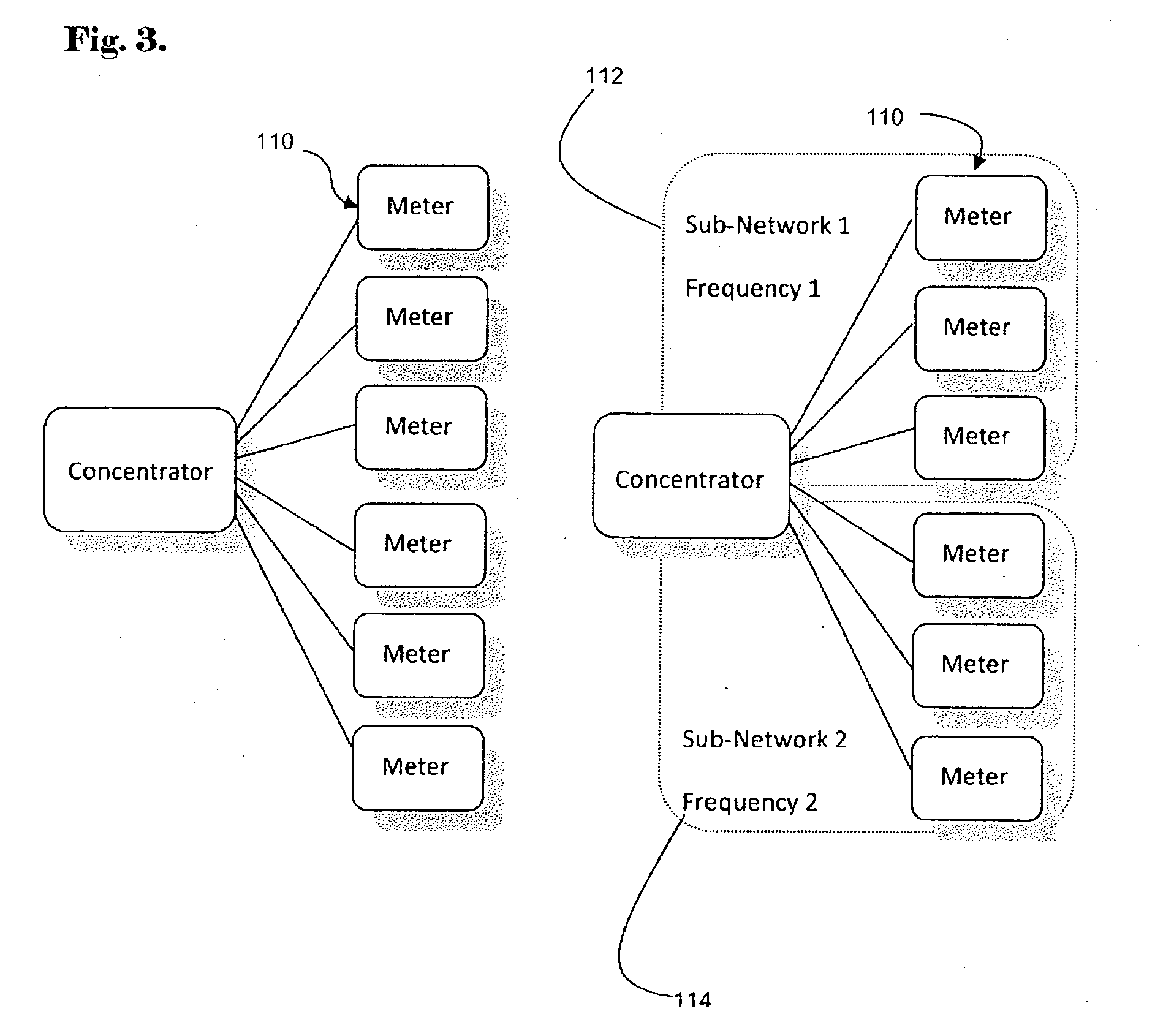
[0017]In embodiments of the second aspect the subdivision of the subnetworks by frequency division allows for improved transaction times for automatic meter reading.
[0024]In embodiments of the sixth aspect fewer coefficients are needed for the equivalent filter bandwidth as well as fewer registers for storage. Furthermore, each filter can be sub-divided and reconfigured to realise two separate narrow band filters or combined to form a higher order single filter. The reconfigurability and reuse of logic has the benefit of significant area and cost savings.

Problems solved by technology

In such systems repeating is often needed due to attenuation and interferences.
This means that completing the readings may not be accomplished within the requisite meter reading interval.
The problems of attenuation that exist at higher frequencies, the presence of large transients, increased cost and limitations due to spectrum allocation in different countries means that the use of higher data rate system in addressing the issue of completing the readings within the requisite time, is either typically difficult to implement or not suitable for automatic meter reading.
Simple communications systems over power lines are often unable to communicate at all in the face of many common types of noise.
Other common problems include attenuation and severe loading which also make transmission difficult.
The above problems are often readily observable however this is not the case with noise in the form of line impedance fluctuation.
The changing of impedance has two undesirable effects.
Firstly, the amplitude of the received signal will often change wildly and in some cases abruptly.
This means that any amplitude information is unreliable and can cause problems with gain control systems.
Secondly, phase information encoded in carrier signals can be distorted by the impedance change due to the phase delay introduced by capacitive and inductive elements.
Abrupt impedance variation can make binary phase shift keying demodulation virtually impossible due to the fact that all of the information is encoded in the phase.
Another common source of interference on the power line is tonal noise.
Tonal noise from devices such as switch mode power supplies conduct harmonics onto the power line that often block communications on a single carrier frequency.
Early power line communication devices had single frequency operation and had the problem of never being able to communicate on power line networks if such switching power supplies existed.
Problems also exist with severe notches in the power line frequency response from point to point.
Systems of this type have provided only limited success.

Method used

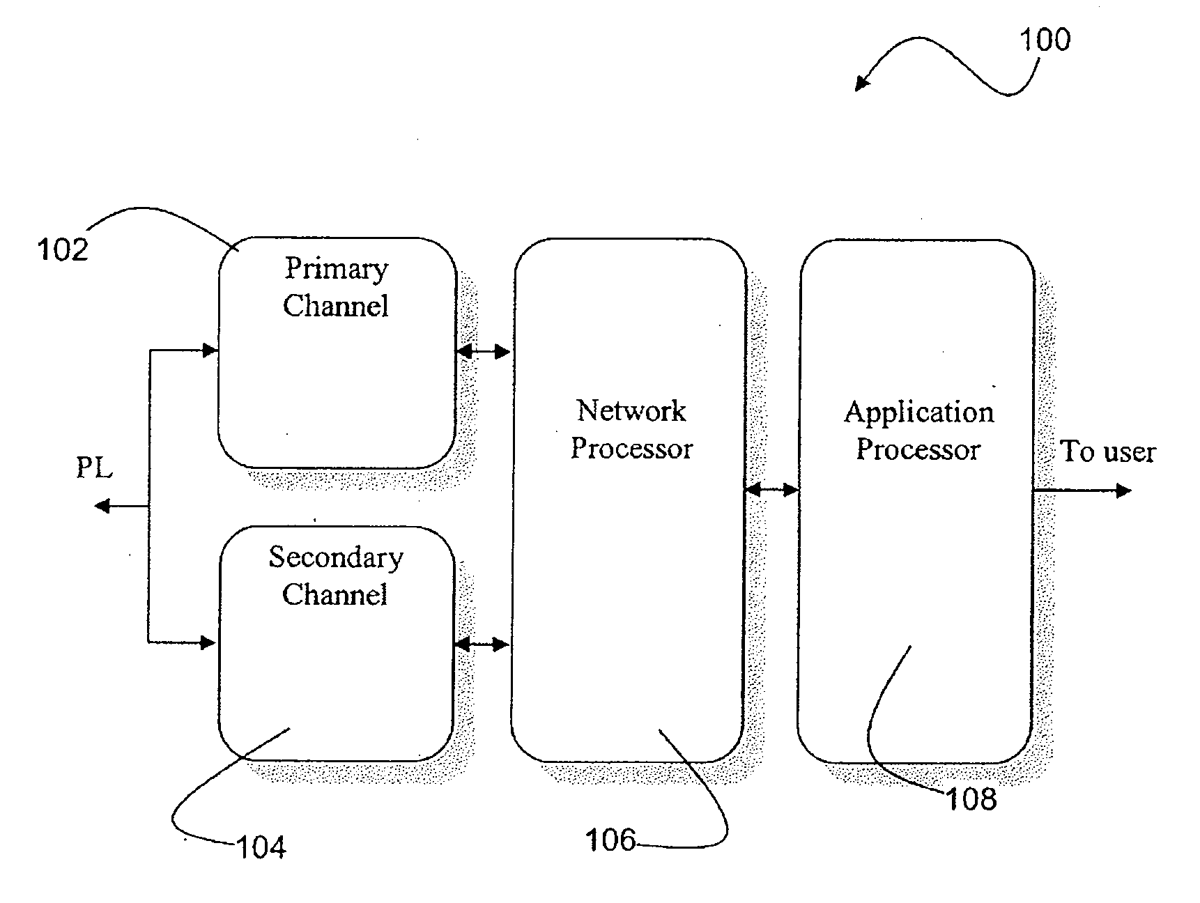
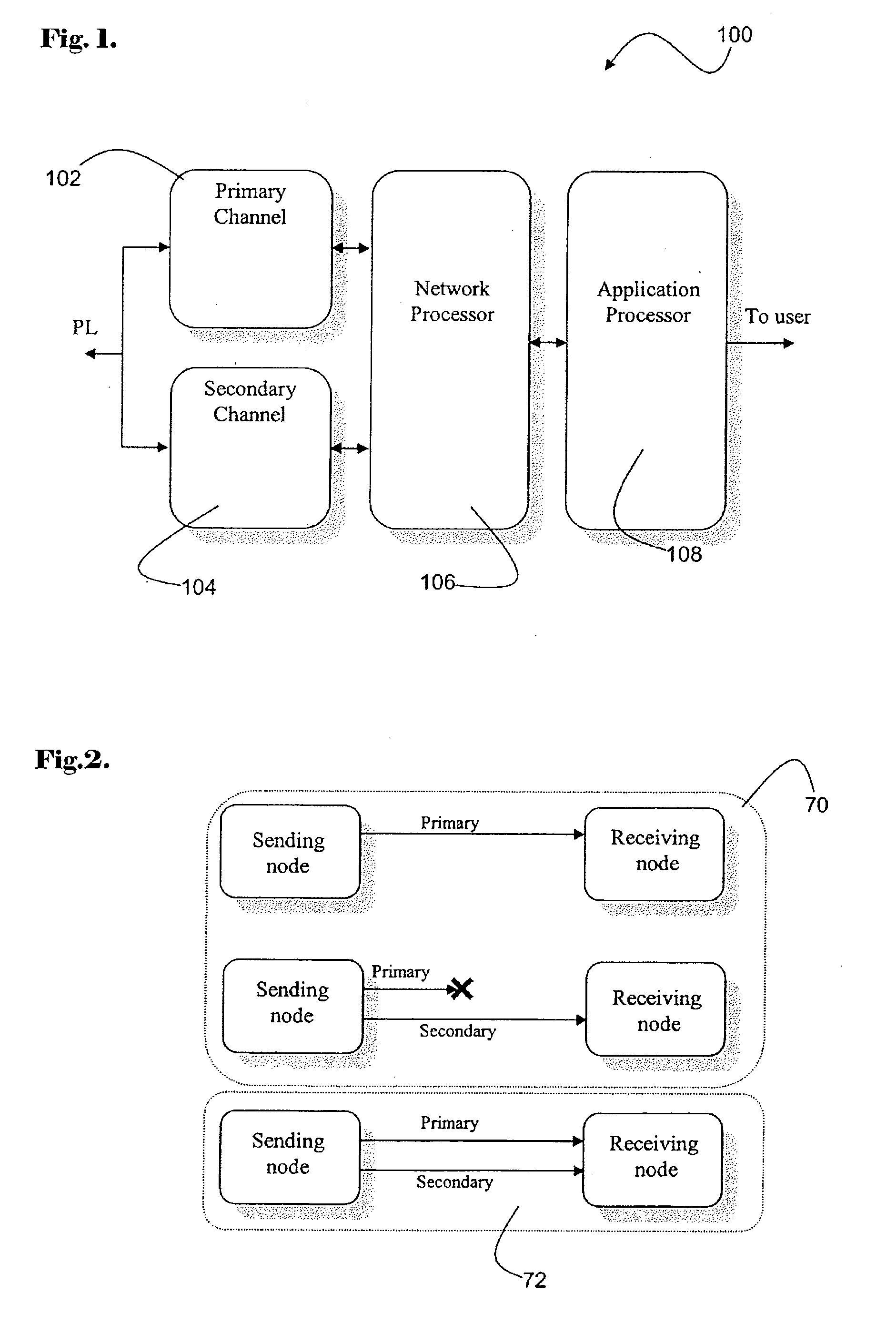

Image

  • Communication methods and devices
  • Communication methods and devices
  • Communication methods and devices

Examples


example network

[0084]An example of the time taken to read 500 meters in a preferred AMR system is provided. Notably, the calculations are simplified and only take into account basic errors and otherwise demonstrate the operation of the system. The calculations are as follows:

Assumptions

[0085]

Frequency A86 kHz (3591 bps)Frequency B79 kHz (3306 bps)Request Time70 msResponse Time200 ms (50 bytes overestimation)Average packet error rate10%Percentage no routes30% (150 meters)Percentage one route20% (100 meters)Percentage two routes20% (100 meters)Percentage three routes30% (150 meters)Subnet size25 metersRoute delay2 msNote:transmission times are taken at the lowest speed (3306 bps).


PUM


Abstract

In one arrangements there is provided a communications method (10). The method (10) includes sending data (14) in a phase shift keyed form (16) over a power line carrier (22) and sending the same data (14) in a frequency shift keyed form (20) over the same power line carrier (22).

Description

FIELD OF THE INVENTION[0001]The present invention relates to the field of communication methods and devices. In particular arrangements the present invention relates to the field of power line communication networks.[0002]The disclosure of Australian Provisional Application 2007903688, filed 10 Jul. 2007, from which priority is claimed, is hereby fully incorporated by reference, in its entirety, and for all purposes.[0003]The disclosure of related application PCT / AU2006 / 000530, filed 26 Apr. 2006, is hereby fully incorporated by reference, in its entirety, and for all purposes.BACKGROUND ART[0004]Power line networks in many countries have a large number of houses connected to a single distribution transformer. In networks of this kind an automatic meter reading interval of 30 minutes may necessitate a transaction completion time of a less than a few seconds. In such systems repeating is often needed due to attenuation and interferences. This means that completing the readings may no...

Claims


Application Information

Patent Timeline
IPC IPC(8): G08C15/02H04B1/38
CPCH04B2203/5433H04B3/542
Inventor BANNISTER, STUART ROSSCUI, SONG
Owner SEMITECH SEMICON PTE
Learn More