MEMS time-of-flight thermal mass flow meter

a mass flow meter and time-of-flight technology, applied in the direction of volume/mass flow measurement, measurement devices, instruments, etc., can solve the problems of substantial performance alteration, failure of operation, and variation of thermal response, and achieve the effect of superior passivation technique and low surface energy

Active Publication Date: 2014-08-05
M TECH INSTR HLDG
View PDF3 Cites 8 Cited by
  • Summary
  • Abstract
  • Description
  • Claims
  • Application Information

AI Technical Summary

Benefits of technology

[0008]For traditional time-of-flight sensor design, the heater and sensing element are made of two platinum metal wires in most cases. The wires are installed in the middle way of the flow path. During flow measurement, both heater and sensing element are having electric current passed through. Such a configuration is very vulnerable to humidity as the moisture could cause the change of the thermal conductivity of the medium leading to the variation of thermal response and substantial performance alteration. Particles with high flow speed could damage the wires and cause failure of operation. In recent years, time-of-flight sensors made by MEMS technology have been discussed. For the time-of-flight MEMS flow sensor design, both heater and sensing element are disposed on a heat-isolated membrane. The sensor can be installed with its surface in parallel with the flow direction in designated flow channel such that it would be less vulnerable to particle impact. Furthermore, the surface of the elements can be passivated with an electrically isolative but thermal conductive layer which makes the sensor withstands humidity better. Furthermore, the micromachined fabrication method can offer a very precise and consistent distance between the micro-heater and micro-sensing elements which can provide a higher accuracy for the flow measurement compared to conventional time-of-flight thermal sensor.
[0011]The heat dissipation or absorption rate of heater and sensing thermistors in a static fluid perceptibly depends on the fluid thermal properties which significantly rely on the fluid density, and fluid components, etc. In the present preferred embodiments, the heater and sensing thermistors both are standing on a thermally isolated thin film membrane. There are four open slots on the membrane along each side of thermistors which are used to block the lateral heat conduction on membrane between the heating and sensing elements. Both thermistors are encapsulated with a 0.3˜0.5 micron thick dielectric film as passivation layer, which is also comprised as part of the suspending membrane. Compared to the conventional two-wire time-of-flight thermal sensor, the micromachined time-of-flight thermal sensor apparently provided a superior passivation technique to cope with the challenges from rush environments. Above the dielectric film, a thin layer of fluorocarbon coating is deposited onto the whole device to make the surface of device become hydrophobic and have low surface energy. The thin hydrophobic fluorocarbon coating will significantly prevent alien particles or debris or liquid materials to stick on device surface which could degrade device operation. The cavity underneath the suspending membrane is fabricated by anisotropic bulk etching of the silicon substrate.
[0012]In a normal operation situation, the micro-heating element is located on the upstream position of flow media while the micro-sensing element is disposed on the downstream position. In the current invention, the micro-heating and micro-sensing elements could be fabricated in an identical design with same materials. Therefore, with the flexibility from driving circuit, the meter in current invention can provide a bi-direction flow measurement capability as well.

Problems solved by technology

Such a configuration is very vulnerable to humidity as the moisture could cause the change of the thermal conductivity of the medium leading to the variation of thermal response and substantial performance alteration.
Particles with high flow speed could damage the wires and cause failure of operation.
This technique has the merit of a simpler circuitry, except the disadvantage is that for lower flow speed, the pulse signal detected by the sensing element could be very blurry.
And its precise traveling time is hard to be determined; therefore the accuracy could be questionable.

Method used


Image

  • MEMS time-of-flight thermal mass flow meter
  • MEMS time-of-flight thermal mass flow meter
  • MEMS time-of-flight thermal mass flow meter

Examples


Embodiment Construction

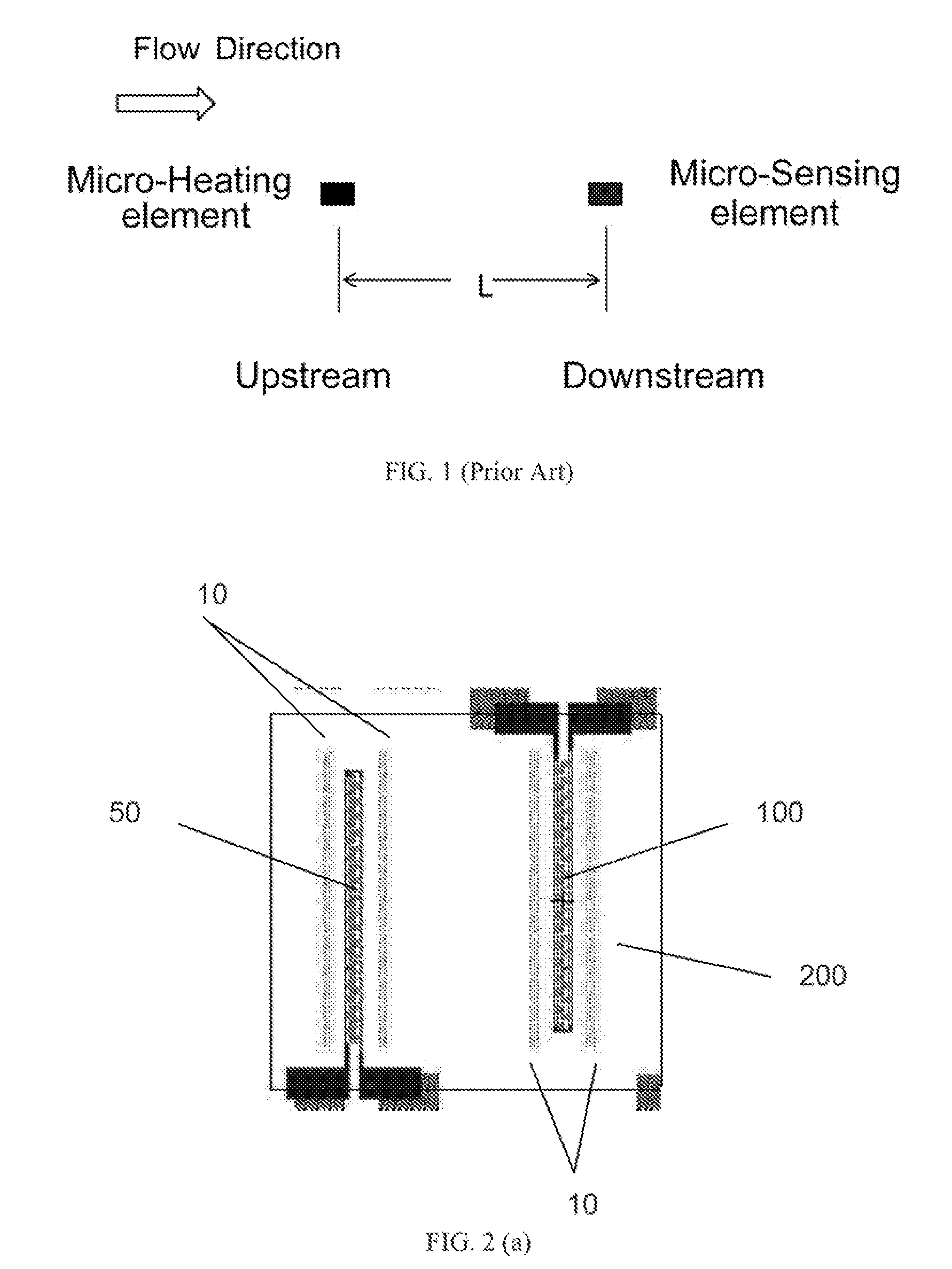
[0022]FIG. 1 illustrates the basic operation principle of thermal time-of-flight sensor. The micro-heating element is disposed at the upstream of flow media while the micro-sensing element is located at the downstream of flow media. If the distance between two elements is L and the traveling time of heat wave travel from heater to sensor is t, then the flow speed, V, will be solved easily as L / t.

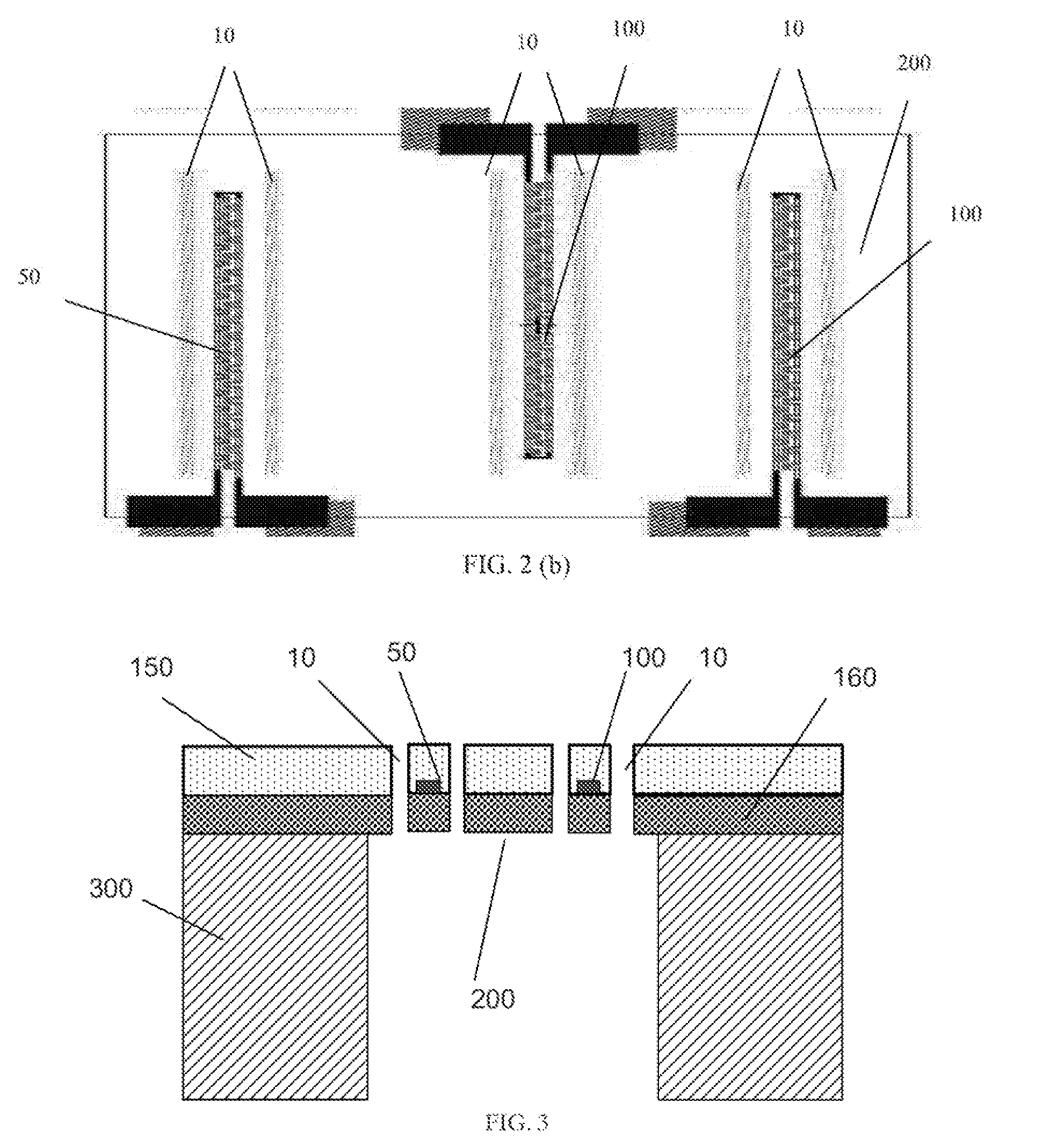
[0023]FIG. 2 (a) illustrates a top view of preferred sensor topology. A time of flight thermal sensor is mainly composed by one heater and one sensing element only. The serpentine shape thermistors 50 and 100 are the micro-heating and micro-sensing elements made of high temperature coefficient of resistance (TCR) materials such as Pt, Au, MgO, and TaN etc. Component 50 and 100 are disposed on top of a suspending membrane 200 which can provide a good thermal isolation property. There are two opens slots (components 10) on the membrane along each of thermistors which can block off the lateral ...


PUM


Abstract

An apparatus comprising a micromachined (a.k.a. MEMS, Micro Electro Mechanical Systems) silicon flow sensor, a flow channel package, and a driving circuitry, which operates in a working principle of thermal time-of-flight (TOF) to measure gas or liquid flow speed, is disclosed in the present invention. The micromachining technique for fabricating this MEMS time-of-flight silicon thermal flow sensor can greatly reduce the sensor fabrication cost by batch production. This microfabrication process for silicon time-of-flight thermal flow sensors provides merits of small feature size, low power consumption, and high accuracy compared to conventional manufacturing methods. Thermal time-of-flight technology in principle can provide accurate flow speed measurements for gases regardless of its gas compositions. In addition, the present invention further discloses the package design and driving circuitry which is utilized by the correlated working principle.

Description

BACKGROUND OF THE INVENTION[0001]1. Field of the Invention[0002]The present invention relates to an apparatus and a method for measuring gas or liquid flow rate according to the preambles of the independent claims. More particularly, the present invention discloses the design and manufacturing of comprising components of a thermal flow meter with a working principle based on time-of-flight methodology which can provide a flow speed measurement regardless the composition of flow media.[0003]2. Description of the Related Art[0004]Various gas or liquid flow meters with different working principles have been heretofore developed and commercially available on market. The gas and liquid flow meters are broadly deployed in various gas control and monitoring industries such as chemical, food process, beverage, medical, pharmaceutical, and utility gas applications. Among various technologies, however, most of the measuring technologies are very limited to the consistency of its flow media co...

Claims


Application Information

Patent Timeline
Patent Type & Authority Patents(United States)
IPC IPC(8): G01F1/708G01F1/68G01F1/72G01F1/7084
CPCG01F1/7084G01F1/72
Inventor HUANG, LIJIWU, XIAOZHONGYAO, YAHONGCHEN, CHIH-CHANG
Owner M TECH INSTR HLDG
Why Eureka
Try Eureka