Damping valve arrangement for a vibration damper

a technology of vibration damper and damper, which is applied in the direction of functional valve types, shock absorbers, machines/engines, etc., can solve the problems of annoying knocking noise, and achieve the effect of reducing the knocking nois

Inactive Publication Date: 2014-08-05
ZF FRIEDRICHSHAFEN AG
View PDF11 Cites 4 Cited by
  • Summary
  • Abstract
  • Description
  • Claims
  • Application Information

AI Technical Summary

Benefits of technology

[0009]It is thus an object of the present invention to propose a damping valve arrangement in which a reduction of knocking noise is achieved.
[0011]The pressing force of the valve disk acting on the damping valve body can be changed by a defined magnitude by means of the spring force of the spring element acting in opposition to the closing force. The damping medium pressure acting against the spring force of the valve disk is reinforced by the spring force of the spring element. Accordingly, a partial opening of the valve disk is made possible already at a low pressure level. The pressure compensation takes place at a lower damping medium pressure, which considerably reduces any knocking noise that may occur.
[0012]As the damping medium pressure decreases, the valve disk acted upon by the closing force closes again. The spring force of the spring element opposes the closing force of the valve disk and slows down the closing process of the valve disk. This appreciably reduces the noise developing during a closing process of the valve disk.
[0015]By constructing the spring element with spring levers of different length as suggested in another preferred embodiment, the spring force can be distributed on the valve disk asymmetrically. This changes the opening behavior and the closing behavior of the valve disk. The valve disk no longer opens abruptly, but rather starting with the area which is acted upon by the greatest spring force by the spring element. The closing of the valve disk starts with the area which is acted upon by the smallest spring force. This opening behavior substantially reduces the knocking noises because the pressure compensation can no longer take place abruptly, but rather is initiated through the spring element in a controlled manner. The same effect can be achieved by a radially asymmetrical construction of the spring levers of the spring element as suggested in two other preferred embodiments.
[0016]According to yet another advantageous embodiment, the damping valve body and the spring element are constructed so as to be fixed with respect to rotation relative to one another radially with reference to the center axis. This prevents a radial displacement of the two elements.
[0018]In vibration dampers which are often subject to extreme loads, the spring element must have a greater material thickness than in vibration dampers which are only rarely, if ever, exposed to extreme loads. In this connection, the spring force likewise increases as the material thickness increases. But since the spring force must be less than the closing force of the valve disk, the valve disks must also be constructed so as to be thicker. According to another advantageous embodiment, when the spring levers of the spring element are oriented at least partially in circumferential direction with respect to the center axis of the damping valve body, the spring levers can be constructed so as to be longer and, accordingly, the spring force of the spring element can be reduced. Therefore, standardized valve disks can be used even in vibration dampers which are often exposed to extreme loading.

Problems solved by technology

The immediate closing of the valve disk and the abrupt pressure compensation cause annoying knocking noises when the valve disk is opened.

Method used


Image

  • Damping valve arrangement for a vibration damper
  • Damping valve arrangement for a vibration damper
  • Damping valve arrangement for a vibration damper

Examples


Embodiment Construction

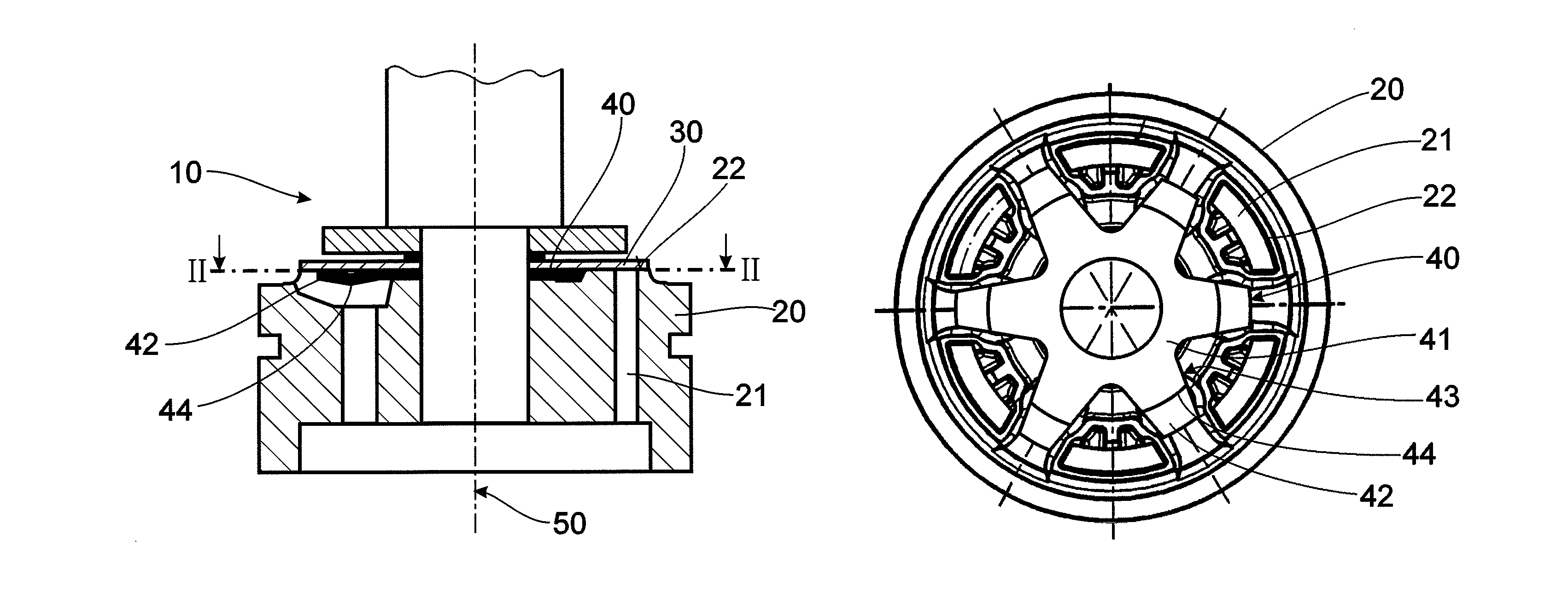
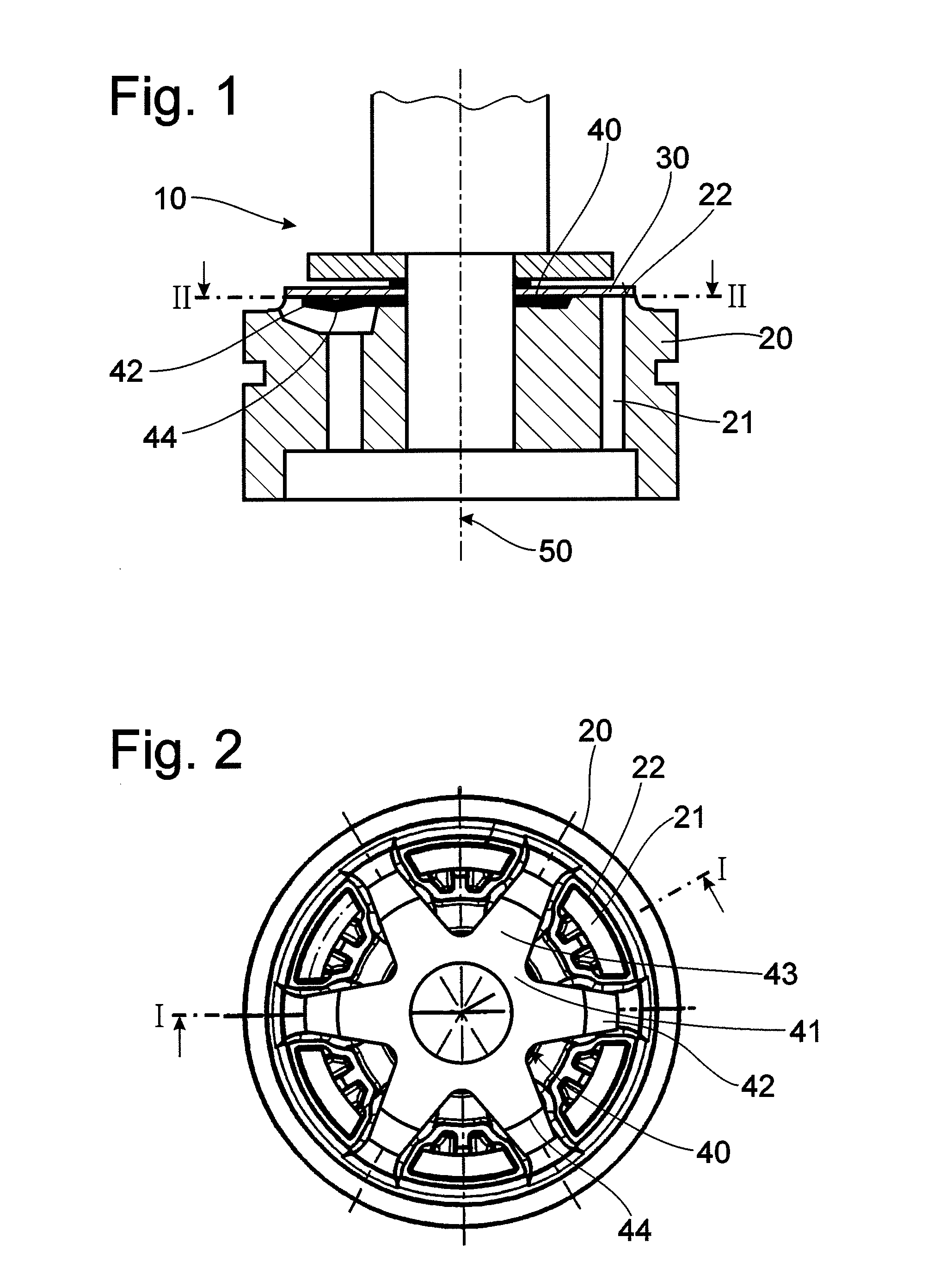
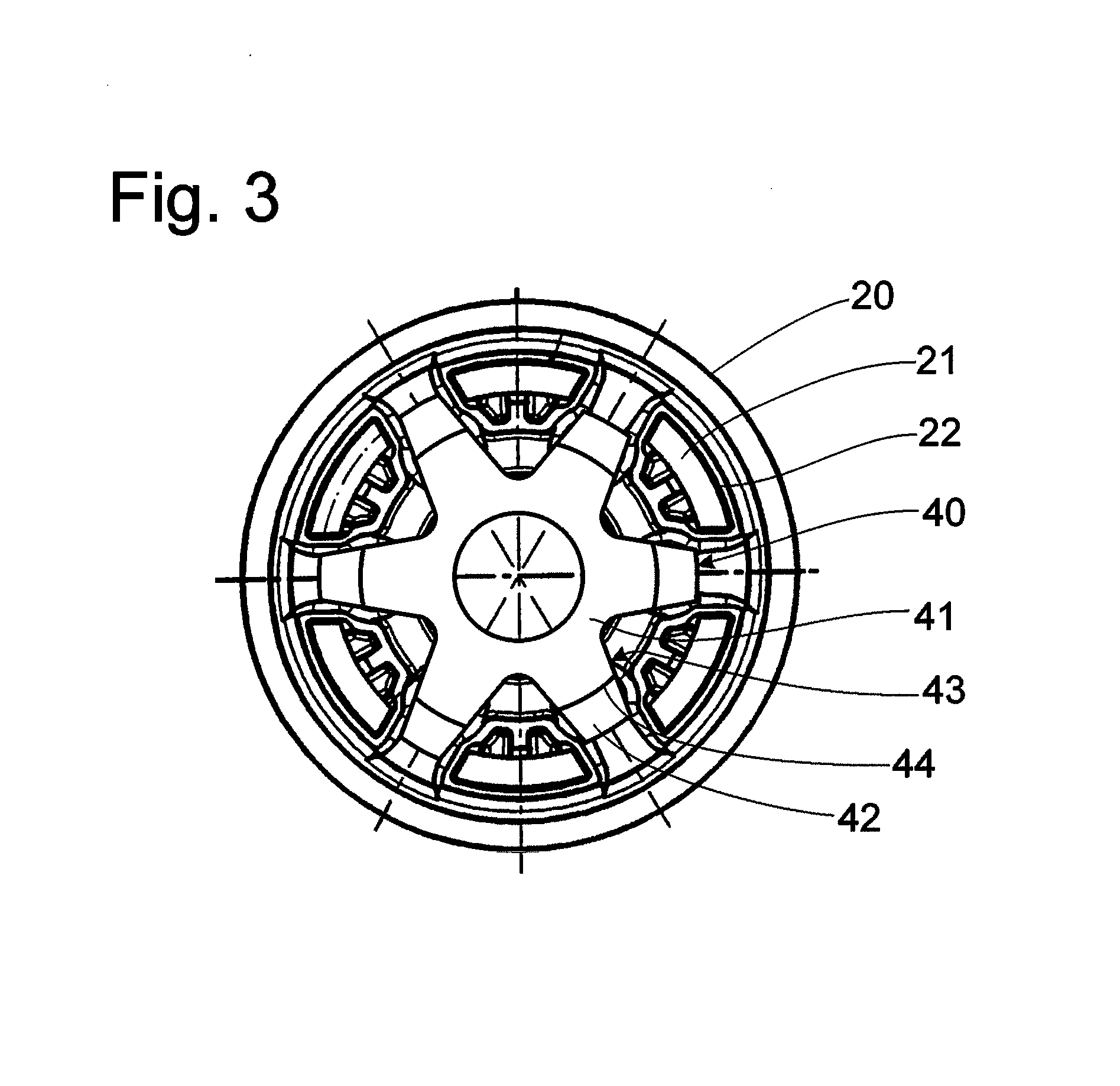
[0026]The drawings show a damping valve arrangement according to the invention which is constructed as a piston valve. Another type of construction, such as a bottom valve, is not shown in the drawings but is also possible. FIGS. 1 to 5 all show a damping valve arrangement 10 according to the invention for a vibration damper; damping medium flows through the damping valve arrangement 10. The damping valve arrangement 10 shown in FIGS. 1 to 3 comprises a damping valve body 20 having a plurality of through-flow openings 21 for the damping medium. FIG. 1 shows a valve disk 30 which is pre-loaded at the damping valve body 20. The valve disk 30 at least partly covers the through-flow openings 21 in the damping valve body 20 under the influence of a closing force.

[0027]The valve disk 30 is not shown in FIGS. 2 to 5 because a clear view of the spring element 40 lying below it would be obstructed in the selected view. A spring element 40 is shown in FIGS. 1 to 5. The spring element 40 has a...


PUM


Abstract

A damping valve arrangement for a vibration damper includes a damping valve body, which has at least one through-flow opening for the damping medium, and at least one valve disk which at least partly covers the through-flow openings under the influence of a closing force. The damping valve arrangement includes at least one spring element which has at least one supporting portion axially supported at another structural component part of the damping valve arrangement, and at least one spring portion disposed at a distance from the supporting portion and which introduces a spring force into the valve disk at least indirectly, wherein the spring force of the spring element is directed counter to the closing force acting on the valve disk, and wherein the spring force of the spring element is less than the closing force of the valve disk.

Description

BACKGROUND OF THE INVENTION[0001]1. Field of the Invention[0002]The present invention is directed to a damping valve arrangement for a vibration damper having a damping medium flowing through the damping valve arrangement, and wherein the damping valve arrangement includes a damping valve body, which has at least one through-flow opening for the damping medium, and at least one valve disk which is arranged at the damping valve body and which at least partly covers the through-flow openings in the damping valve body under the influence of a closing force.[0003]2. Description of the Related Art[0004]A damping valve arrangement of the type mentioned above for a vibration damper is known from U.S. Pat. No. 6,401,755.[0005]A damping valve arrangement for a vibration damper of this type generally comprises a damping valve body, which has at least one through-flow opening for the damping medium, and at least one valve disk arranged at the damping valve body. The valve disk at least partly ...

Claims


Application Information

Patent Timeline
Patent Type & Authority Patents(United States)
IPC IPC(8): F16K21/04F16K17/26F01L3/10F16K24/00F16F9/34F16K15/00F16K17/00F16F9/348F16F9/56F16F9/50F16K15/14
CPCY10T137/7779Y10T137/784F16F9/3485Y10T137/789Y10T137/7843
Inventor HANDKE, GUNTHERLIEBLEIN, KLAUSFRANK, THOMAS
Owner ZF FRIEDRICHSHAFEN AG
Why Eureka
Try Eureka