Eureka AIR delivers breakthrough ideas for toughest innovation challenges, trusted by R&D personnel around the world.

Tensioner

a technology of tensioner and tension lever, which is applied in the direction of gear vibration/noise damping, belt/chain/gearring, gear, etc., can solve the problems of increased production cost, increased chain tension, and increased chain tension, so as to achieve the effect of reducing the amount of backlash, preventing noise or vibration, and reducing the amount of chain tension

Active Publication Date: 2021-04-20
TSUBAKIMOTO CHAIN CO
View PDF27 Cites 0 Cited by
  • Summary
  • Abstract
  • Description
  • Claims
  • Application Information

AI Technical Summary

Benefits of technology

[0008]The present invention solves these problems, its object being to provide a simple-structured tensioner that generates less knocking noise at the start-up of the engine and prevents an excessive chain tension, severe friction, noise, or vibration during the running of the engine, while also reducing production costs.
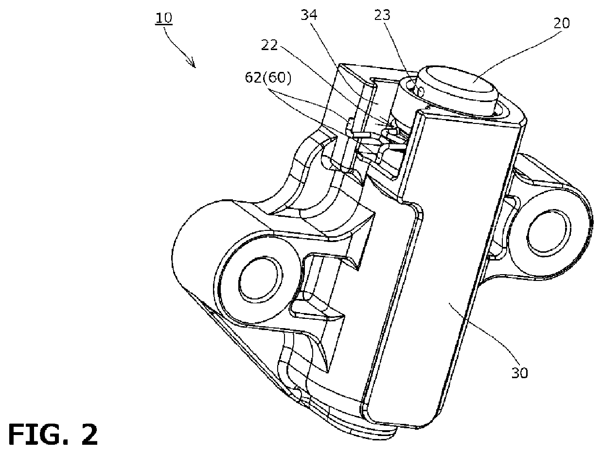
[0020]According to another aspect of the present invention, a second oil pressure chamber formed between the rear-side restriction member and an inner wall of the housing is formed on the rear side of at least part of the rear-side restriction member. Thus it is possible to stop forward movement of the rear-side restriction member with a negative pressure created inside the second oil pressure chamber when the rear-side restriction member attempts to move forward, so that the state in which the rear-side restriction member has moved to the rear side can be stably maintained during the running of the engine when oil is supplied to the tensioner.

Problems solved by technology

The problem with the inventions according to Japanese Patent Application Laid-open No. 2011-27124 and Japanese Patent Application Laid-open No. 2012-251594 was that the backlash amount was controlled with the use of frictional force between the components, which necessitated precise machining of these components and led to an increased production cost.
Another problem with the inventions according to Japanese Patent Application Laid-open No. 2011-27124 and Japanese Patent Application Laid-open No. 2012-251594 was that the plunger could not move rearward until the load applied from the chain to the plunger reaches a certain magnitude.
During the period before the plunger moves rearward, severe friction may occur between the chain and the tensioner lever, or large noises may be generated.

Method used


Image

  • Tensioner
  • Tensioner
  • Tensioner

Examples


second embodiment

[0077]In the second embodiment, the front-side restricting part 71 is formed integrally with the housing 30 as shown in FIG. 9. More specifically, the front-side restricting part 71 is formed to protrude in an annular shape from an inner circumferential surface of the housing hole 31 at the front end of the housing hole 31.

first embodiment

[0078]The front-side restricting part 71 has a front-side restricting surface 71a formed as a flat surface perpendicular to the front to back direction as with the

[0079]The housing hole 31 in the second embodiment is formed to open on the rear side too, as shown in FIG. 9. The housing hole 31 includes, as shown in FIG. 9, a large-diameter hole on the rear side, a front-side small-diameter hole continuously and coaxially formed on the front side of the large-diameter hole, and a stepped portion formed between these large-diameter hole and small-diameter hole. Therefore, the rear-side restriction sleeve 72 and restriction spring 73 can be set inside the housing hole 31 from the rear side of the housing 30.

[0080]In line with this, the tensioner 10 of the second embodiment includes a spring receiving member 90 made of metal or the like, and a resilient retainer 91 made of metal or the like, as components for preventing the rear-side restriction sleeve 72 and restriction spring 73 from f...


PUM


Abstract

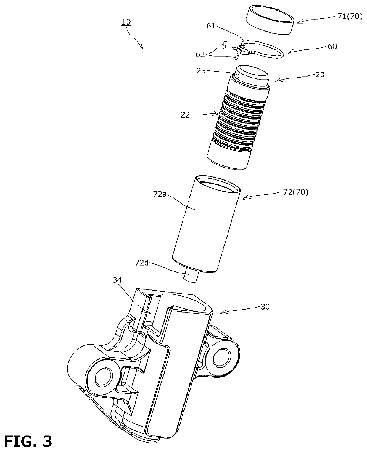
To provide a simple-structured tensioner that generates less knocking noise at the start-up of the engine and that prevents an excessive chain tension, severe friction, noise or vibration during the running of the engine, while also reducing production costs. The tensioner includes a ring control mechanism that controls the position of a resilient ring. The ring control mechanism includes a front-side restricting part having a front-side restricting surface and capable of restricting forward movement of the resilient ring, and a rear-side restriction member having a rear-side restricting surface and capable of restricting rearward movement of the resilient ring. The front-side restricting part is fixed to or formed integrally with the housing. The rear-side restriction member is disposed movable in a front to back direction relative to the housing and the plunger.

Description

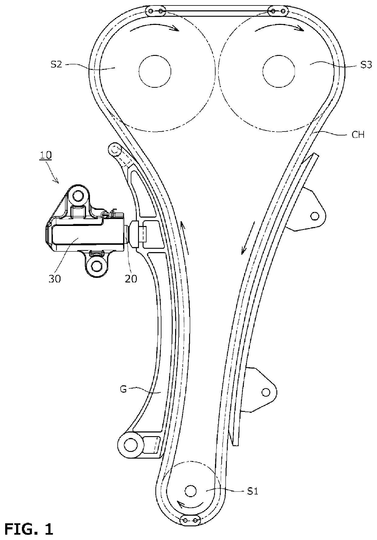
BACKGROUND OF THE INVENTION1. Field of the Invention[0001]The present invention relates to a tensioner that applies appropriate tension to a running chain, belt, or the like.2. Description of the Related Art[0002]It has been common practice to use a tensioner for maintaining correct tension of a chain or the like. For example, a chain guide mechanism has been known, which slidably guides, by means of a tensioner lever, a drive chain such as an endless roller chain passing over respective sprockets of a crankshaft and a cam shaft inside an engine room, and which uses a tensioner to bias the tensioner lever to maintain appropriate tension of the chain or the like.[0003]Such a tensioner normally restricts backward movement of a plunger by a hydraulic damping effect achieved by supplying oil into an oil pressure chamber formed between the plunger and a housing hole. However, the damping does not work until the pressure oil is supplied, for example when the engine has just been started. ...

Claims


Application Information

Patent Timeline
Patent Type & Authority Patents(United States)
IPC IPC(8): F16H7/08
CPCF16H7/0848F16H2007/0806F16H2007/0808F16H2007/0817F16H2007/0853F16H2007/0855F16H2007/0859F16H2007/0895F16H2007/0897F16H2007/0812F16H2007/0893F16H2007/185F16H2007/0872F16H7/08F16H7/0829F16H57/0006
Inventor KUREMATSU, YUJI
Owner TSUBAKIMOTO CHAIN CO
Why Eureka
Eureka Blog
Learn More