Orbital, non-reciprocating, internal combustion engine

Active Publication Date: 2012-04-24
LOCKSHAW JAMES +1
View PDF27 Cites 10 Cited by
  • Summary
  • Abstract
  • Description
  • Claims
  • Application Information

AI Technical Summary

Benefits of technology

[0012]Other features and advantage of the Circle Cycle™ engine include ease of cooling. In general in the Otto engine cooling is achieved by blowing air across cooling fins on the cylinders or by encasing the cylinders in a water jacket and recirculating water through the jacket and an air cooled radiator; this uses engine energy to pump the water or blow the air. The piston in this arrangement is cooled by heat transfer through the cylinder wall. In the invention engine the piston leaves its cylinder completely after the power stroke, so that both piston and cylinder are exposed to cooling air that has a natural flow in the engine cavity, and minimal engine power is used for cooling.
[0013]The Circle Cycle™ engine is in one embodiment operable by a liquid combustible fuel such as gasoline, diesel, biodiesel, etc. wherein an exhaust valve is used to capture exhaust gases for pollution control. In a second embodiment the engine is operable with gaseous combustible fluids such as natural gas, propane, etc. Because these fuels are low in smog producing emissions, as much as 77% less per EPA data, this second embodiment does not require intake or exhaust valves and offers increased engine efficiency and simplicity.
[0014]In either of the above and in other embodiments, the basic d

Problems solved by technology

The connecting rod, traveling with the piston and articulating at the wrist pin and orbiting at the crankshaft presents a changing angular force that results in side loading of the piston against the cylinder wall.
This causes frictional losses.
Because

Method used


Image

  • Orbital, non-reciprocating, internal combustion engine
  • Orbital, non-reciprocating, internal combustion engine
  • Orbital, non-reciprocating, internal combustion engine

Examples


Embodiment Construction

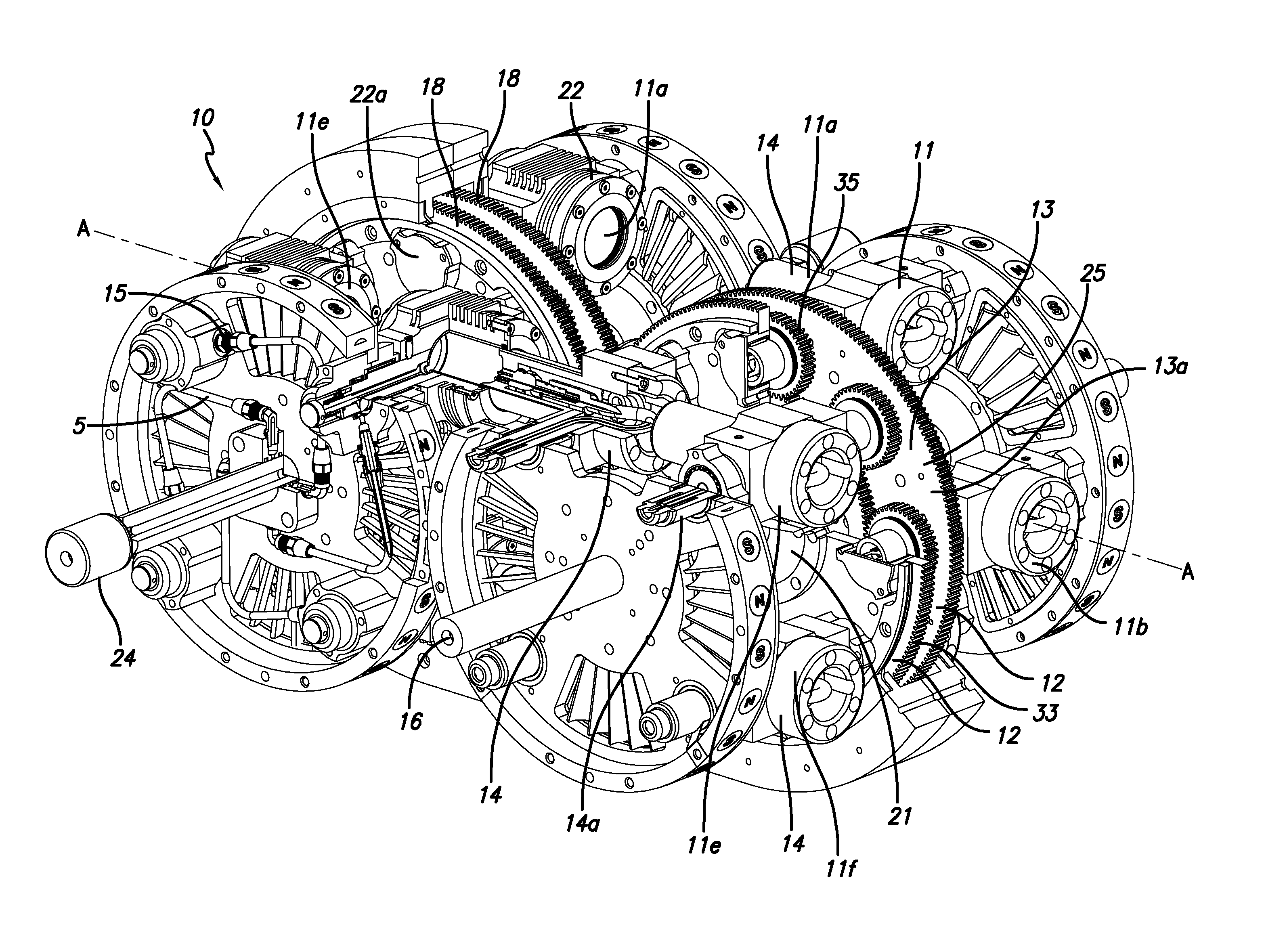
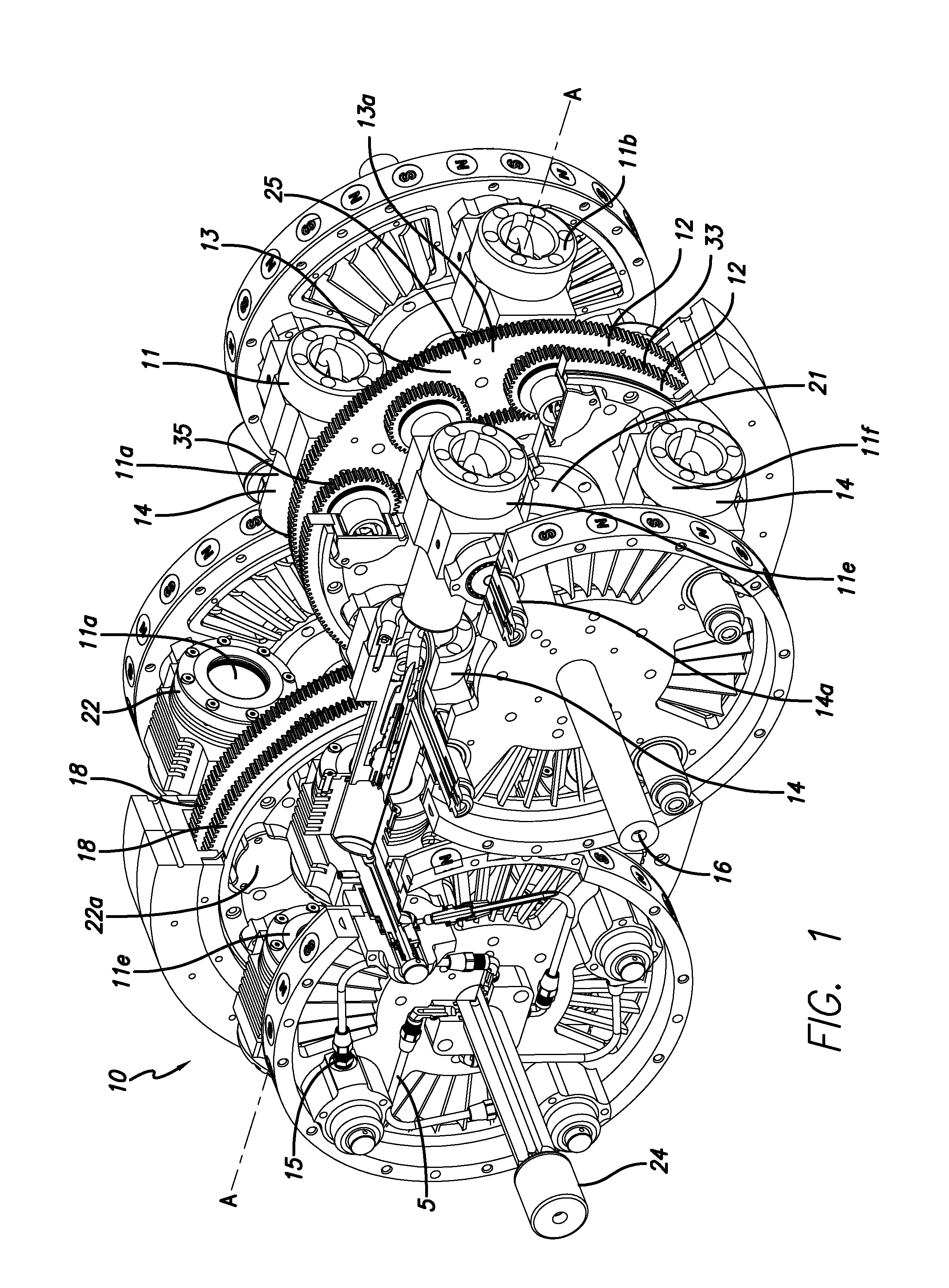
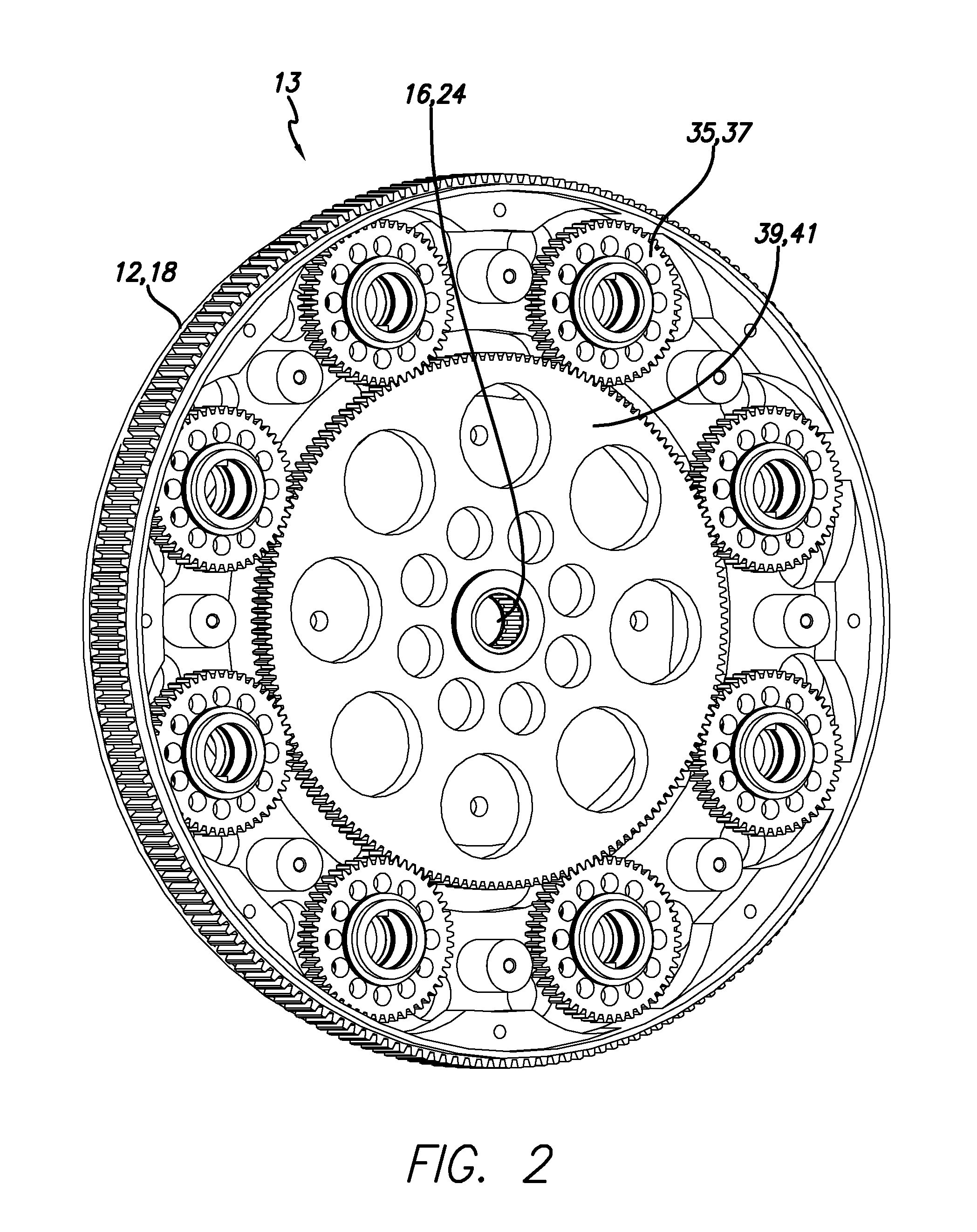
[0033]With reference now to the drawings in detail, and particularly FIGS. 1-7, a combustible fluid operated orbital engine is shown at 10 comprising plural sets 11 of cooperating cylinder members 22 and piston members 14 arranged at all times in opposed relation on a common longitudinal axis A-A for orbital motion along intersecting counter paths 18a, 12a defined by respective cylinder and piston carrier or drive wheels 12, 18. A gearing structure 13 also carried by the carrier wheels 12, 18 and best shown in FIGS. 1 and 2 serves to rotate the cylinder and piston members 22, 14 counter to their circular motion along paths 18a, 12a whereby their common longitudinal axis A-A relation is maintained despite the wheels circular travel. That is, cylinder and piston members 22, 14 are being carried circularly on their respective carrier wheels 12, 18, See FIG. 7, about axles 24, 16, respectively, but gearing structure 13 acts to rotate the cylinders and piston members about their respecti...


PUM


Abstract

A combustible fluid operated orbital engine has plural sets of cooperating cylinder and piston members with respective parallel axes of rotation, respective cylinder and piston carrier wheels with respective axes of rotation parallel to the members' axes of rotation carrying said members circularly and orbitally and at all times in opposed relation on a common longitudinal axis along intersecting counter paths. Respective gearing structures supported by the cylinder and piston carrier wheels rotate the members counter to their circular motion direction to maintain their opposed relation for their periodic interfittment when their respective paths intersect. A combustible fluid supply is provided to the cylinder member for combustion coincident with the periodic interfittment in engine operating relation. The common longitudinal axes of the cylinder/piston sets are at all times parallel with each other.

Description

CROSS-REFERENCE TO RELATED APPLICATIONS[0001]This application claims the benefit of U.S. Provisional Application Ser. No. 61 / 100,751, filed Sep. 28, 2008. This application is further a continuation in part of U.S. patent application Ser. No. 11 / 735,478 filed Apr. 15, 2007, which application claims the benefit of U.S. Provisional Application Ser. No. 60 / 792,603 filed Apr. 17, 2006. The disclosures of these applications are hereby incorporated by reference.BACKGROUND OF THE INVENTION[0002]1. Field of the Invention[0003]The principal object of the present invention is to improve the efficiency of the Otto Cycle internal combustion engine. The Otto Cycle engine, invented in 1861, has served as the preeminent design for the conversion of chemical energy to mechanical energy over many years. There have been many improvements to this ingenious concept but it still exhibits inefficiencies due to friction, torque and pumping losses.[0004]2. Description of the Related Art[0005]The Otto Cycle ...

Claims


Application Information

Patent Timeline
IPC IPC(8): F02B75/18
CPCF01B13/061F02B57/08F02B57/10F02B75/265
Inventor LOCKSHAW, JAMESGERONDALE, JOSEPH
Owner LOCKSHAW JAMES
Why Eureka
Try Eureka