Media Control Valve

a technology of control valve and media control, applied in the field of media control, can solve the problems of valves that cannot be used, valves that cannot be replaced or substantial repaired, and damage to valves beyond use, and achieve the effects of less sliding friction, less friction, and less friction

Active Publication Date: 2013-05-02
NGUYEN PHUONG TAYLOR
View PDF9 Cites 10 Cited by
  • Summary
  • Abstract
  • Description
  • Claims
  • Application Information

AI Technical Summary

Benefits of technology

[0026]In one aspect of the invention, the media control valve includes a diaphragm which eliminates the piston and piston seal. The diaphragm acts as a membrane that physically isolates and seals the chambers above and below. The pistonless design means that that there is no piston to slide and seal against the cylinder wall. This results in less sliding friction and eliminates one less area where grit can bind the valve. Dust and grit from ambient or a contaminated compressed air line will not bind the valve. The breather vent becomes less critical. In addition, less friction means more of the mechanical forces are available to open and close the valve resulting in quicker, more efficient, and more reliable valve action. Also, the diaphragm designs do not require lubrication, which speeds assembly time and also minimizes the environmental impact from the chosen lubricant.
[0027]In another aspect of the invention, the spool sleeve design has all of the plunger seals and bushings held within the sleeve. This allows removal of all of the seals along with the removal of the sleeve. In some cases, not all but some of the seals are inside the sleeve, which is consistent with one aspect of the invention. Once the spool sleeve is removed, the replacement seals and bushings can be replaced and inspected with relative ease due to the accessibility at both ends of the sleeve. Since each plunger seal is held within its own rigid cavity, held on three sides and not stacked on top of another seal or loose component, proper alignment is better assured during and after installation.
[0028]It is an important feature of the valve of the subject invention that the rigid assembly between components as is common in the prior art valves has been replaced with a floating design with components being assembled using numerous resilient seals and spacers between rigid members, permitting the assembly to self-center or self-position. This minimizes or even eliminates the tendency of various components to bind during operation, particularly as a result of normal operation and normal wear. This also assures proper alignment of the various components by permitting relative movement between components during operation. The floating design of the subject invention also facilitates in maintenance and repair by permitting the assembly to be disassembled by relying on the relative ease in removing the resilient seals.
[0029]Even in prior art designs having a single plunger seal, the spool design of the subject invention will allow for additional space to include additional plunger seals or wipers which will improve the life and versatility of these valves, as well. Also, the addition of a wiper immediately above the tungsten carbide liner keeps all the grit between carbide-to-carbide surfaces, thus reducing sliding friction and preventing the accumulation of residual grit between the plunger and sleeve.
[0030]In yet another aspect of the invention, the composite sleeve may incorporate a soft urethane or equivalent material to liner or encapsulate a hard abrasion resistant material such as tungsten carbide or hardened stainless steel. The softer thermoplastic liner will allow for easy removal while the hard lining will provide longevity and durability.
[0031]Revising the cavity to have a taper allows the gap relative to the sleeve to increase during extraction or removal thus decreasing the bind and rolling and allow the sleeve to release easily. In addition, a taper, at the same angle as the mating inside surface of the body, can be utilized. This will further ease the release of the sleeve from the body.

Problems solved by technology

One of the most critical issues with remote actuated media control valves is the life of the valve.
The abrasive media can damage the valve beyond use in a short period of time, requiring replacement or substantial repair.
It is not uncommon for any of these valves to malfunction after some use due to the sleeve and plunger locking up, thereby not allowing the plunger to reciprocate within of the sleeve.
In either case when plungers lock up or seize, accelerated wear results on the adjacent components of the valve such as the body, seat, and base.
However, this patent does not address the more frequent mode of failure where the plunger binds against the sleeve, or is seized.
While these designs have been effective at sealing, there are two issues.
In many of these valves it is very difficult to change out the seals due to the deep location of the seals with the inherently gritty environment.
In valves utilizing the multiple plunger seal design, the plunger seals are stacked on top of each other which is a blind install that does not permit visual verification of proper seal alignment or seal installation.
Also, this will create boundaries where two soft surfaces press against each other, and which creates an opportunity for the seals to misalign when stressed during plunger movement or during installation or operation.
First, the stainless jacket on the sleeve wears at the ID more quickly than at the hard liner primarily because of the difference in hardness of the two materials.
Second, the stainless ID section of the sleeve is softer than some of the abrasive media used, such as aluminum oxide grit or hardened steel grit.
These harder particles can dig into the relatively softer yet still rigid stainless steel and cause binding between the plunger and sleeve.
Third, this design permits the accumulation of grit within the plunger-to-sleeve gap.
This is a problem with all plunger-sleeve designs in the airblast industry regardless of their hardness and regardless of their material composition.
Recently, valve designs including an offset sleeve internal diameter and plunger seals of the spooled sleeve have been designed in an attempt to minimize the issue by not allowing or significantly reducing the accumulation of residual abrasives.
The weakness of this design is that it is not tolerant of particulate contamination which is inherent of the dusty and gritty conditions of an airblast environment.
When the breather vent is sized properly, the particulates that pass through and enter the cylinder are not large enough to cause the piston to jam, or seize.
Breather vents are an additional cost and properly sized fine breather vents are even more expensive.
Some end users have even tried to replace the vents with cheaper larger micron vents and have experienced failures.
The second source of grit contamination is from the compressed signal line.
Blast systems with inadequately supplied compressed airflow tend to pull grit from the blast pot or vessel and cause dust and grit to eventually contaminate the compressed air control line.
Typically, in the prior art designs, the piston and piston seal do not function efficiently and fail quickly without lubrication.
Both types of lubrication have a tendency to attract dust which can contribute to the piston to cylinder binding.
This will significantly increase the force required to remove the sleeve from the body.
Also, due to the straight cylinder and mating cavity, the grit continues to roll and slide which creates friction until the sleeve is completely removed.
This makes disassembly relatively difficult.
Generally the wear on these occur due to the sliding and rubbing of the plunger against the inside of the sleeve with abrasive grit between them.
Consequently, the wear is mainly in this area.
However, since it is fused to the tungsten carbide, the still new stainless is discarded along with the worn Tungsten.
Likewise, the sleeve can only be replaced by disassembling the entire valve.

Method used


Image

  • Media Control Valve
  • Media Control Valve
  • Media Control Valve

Examples


Embodiment Construction

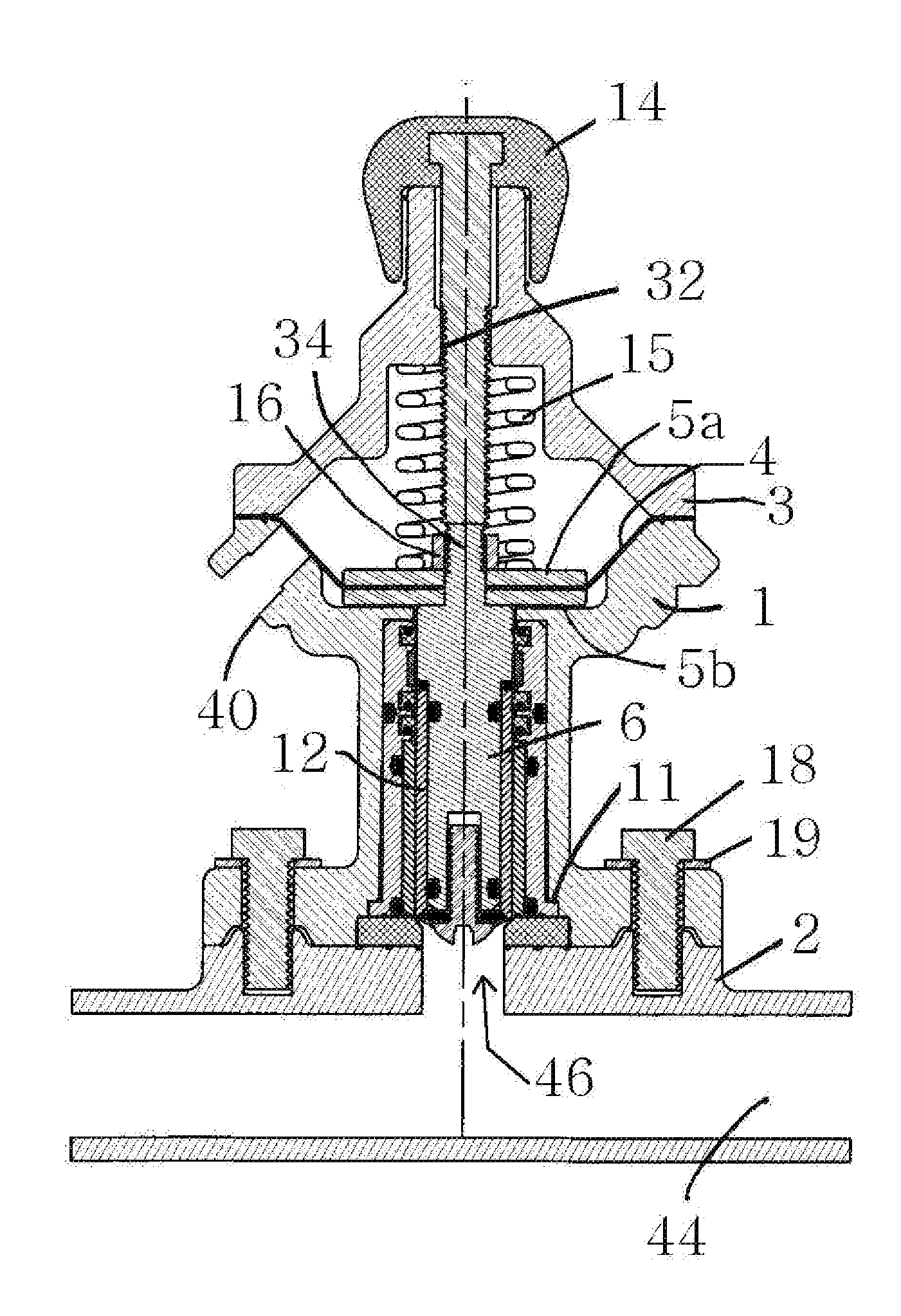
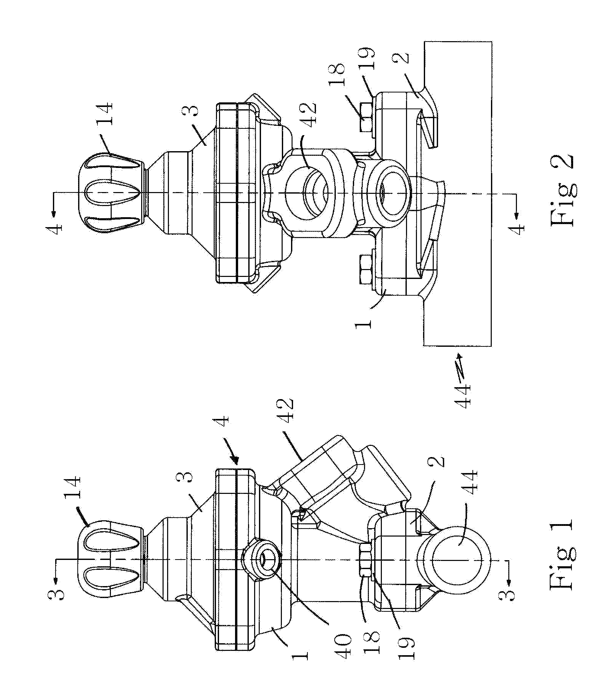
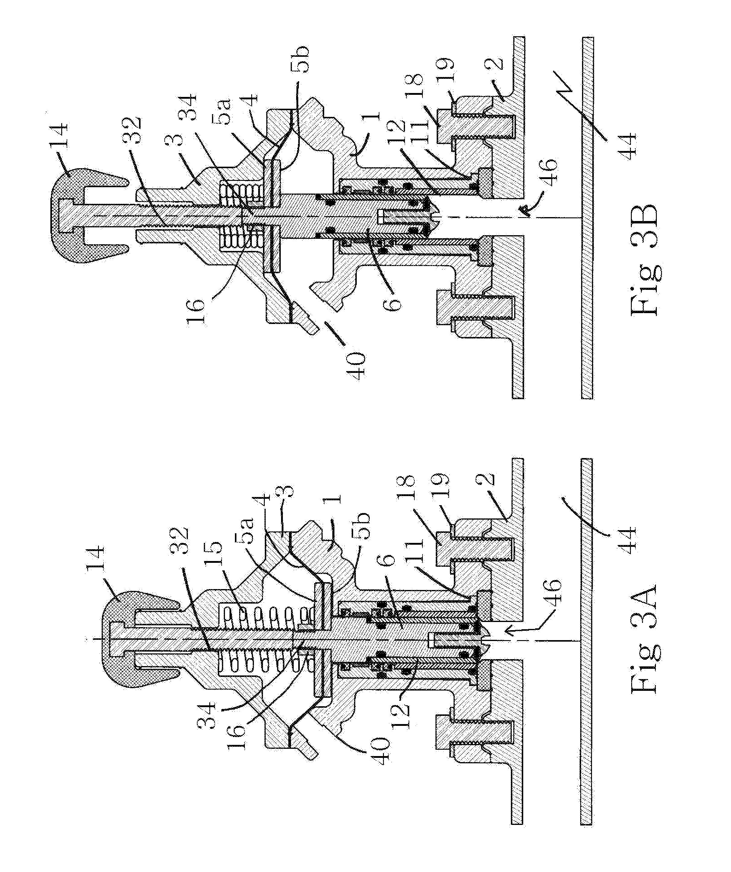
[0044]Referring initially to FIGS. 1, 2, 3A, 3B, 4A and 4B, the valve assembly includes a valve body 1 for housing the valve plunger assembly, the spool sleeve assembly and the lower diaphragm plate 5b (see, for example FIGS. 3A and 3B), as will be explained with reference to FIGS. 5-8. The valve cap assembly 3 is secured to the body 1 and houses the diaphragm 4 (best shown in FIGS. 4A and 4B), upper diaphragm plate 5a and the metering knob assembly terminating in the metering knob 14. The upper valve assembly, comprising the body 1, the cap assembly 3, knob assembly including knob 14 and the internal components are typically secured to the valve base 2 by a series of bolts or similar fasteners 18. Typically, a washer 19 is positioned between each bolt head and the valve body 1, as shown.

[0045]The pressurized indexing air or control fluid is introduced into port 40, as indexed or metered by the position of the metering knob assembly terminating in metering knob 14. Abrasive media is...


PUM


Abstract

A media control valve includes a body, a plunger assembly of multiple components housed in the body with a plunger control valve cap assembly secured to the body for housing a control knob. The body and the plunger assembly include resilient seals between adjacent multiple components of the body and the plunger assembly, respectively, to permit relative movement therebetween. A diaphragm physically isolates and seals the chambers above and below. All of the plunger seals and bushings held within the sleeve. Replacement seals and bushings can be replaced and inspected with relative ease due to the accessibility at both ends of the sleeve. Component parts are assembled using resilient seals to facilitate assembly and repair.

Description

BACKGROUND[0001]1. Field of the Invention[0002]The present invention is related to media control and, more specifically, media control valves used to control the flow of a media into a fluid stream as part of an apparatus for treatment of a surface.[0003]2. Description of the Related Art[0004]A typical manual media control valve is disclosed in U.S. Pat. No. 4,322,058(“the '058 patent”). The valve of the '058 patent is attached to a media vessel and controls the flow of the media from the media vessel into a conduit containing a fluid stream. This conduit terminates in a nozzle. Fluid and media pass through the nozzle at high speed and are typically used to treat surfaces.[0005]A more recent pneumatic actuated media control valve is the pipe side valve shown and described in U.S. Pat. No. 3,476,440 (“the 440 patent”), issued to Thompson, et al on Mar. 30, 1982. The valve described in this patent has been has been widely accepted in applications where the flow of particulate material...

Claims


Application Information

Patent Timeline
Patent Type & Authority Applications(United States)
IPC IPC(8): F16K1/32
CPCF16K3/246
Inventor NGUYEN, PHUONG TAYLOR
Owner NGUYEN PHUONG TAYLOR
Why Eureka
Try Eureka