Tonometer calibration tool

a calibration tool and tonometer technology, applied in the field of noncontact tonometers, can solve the problems of poor simulation of a real eye, rubber eyes developing folds, time-consuming and expensive clinical trials, etc., and achieve the effect of reducing the number of alignment steps and parts association

Active Publication Date: 2014-08-12
REICHERT
View PDF20 Cites 2 Cited by
  • Summary
  • Abstract
  • Description
  • Claims
  • Application Information

AI Technical Summary

Benefits of technology

[0010]The present invention meets the stated needs and improves upon the calibration tool of U.S. Pat. No. 6,679,842 by reconfiguring the calibration tool to mount directly on a nosepiece of the tonometer or on a measurement head of the tonometer to eliminate alignment steps and parts associate therewith.
[0013]In accordance with the present invention, the calibration tool is mounted on the tonometer in fixed relation to the fluid discharge passage to eliminate the need for preliminary alignment.

Problems solved by technology

Conducting clinical trials is time consuming and expensive, and therefore clinical calibration might be conducted with respect to a “master” non-contact tonometer, and the master non-contact tonometer is then used as a calibration standard.
Rubber eyes develop folds during testing and tend to be a poor simulation of a real eye.
Moreover, rubber eyes are expensive and difficult to manufacture because very tight tolerances are necessary.
Finally, the rubber material ages or can be damaged, so that a set of rubber eyes must be constantly recalibrated to maintain reliability.
The tonometer calibration devices and methods mentioned above are delicate, expensive, unstable, and / or difficult to use, and they cannot be traced to an absolute pressure standard such as that provided by a water column or precision pressure calibrator.
While the calibration tool of the '842 patent has greatly simplified calibration procedures, it has the drawback that it is time consuming to set-up.
The preliminary alignment steps are time consuming, and they require additional parts such as the glass sphere, mirror, and precision slide mechanism that add size and cost to the calibration tool.
If proper alignment is not carried out, calibration accuracy may suffer.

Method used


Image

  • Tonometer calibration tool
  • Tonometer calibration tool
  • Tonometer calibration tool

Examples


first embodiment

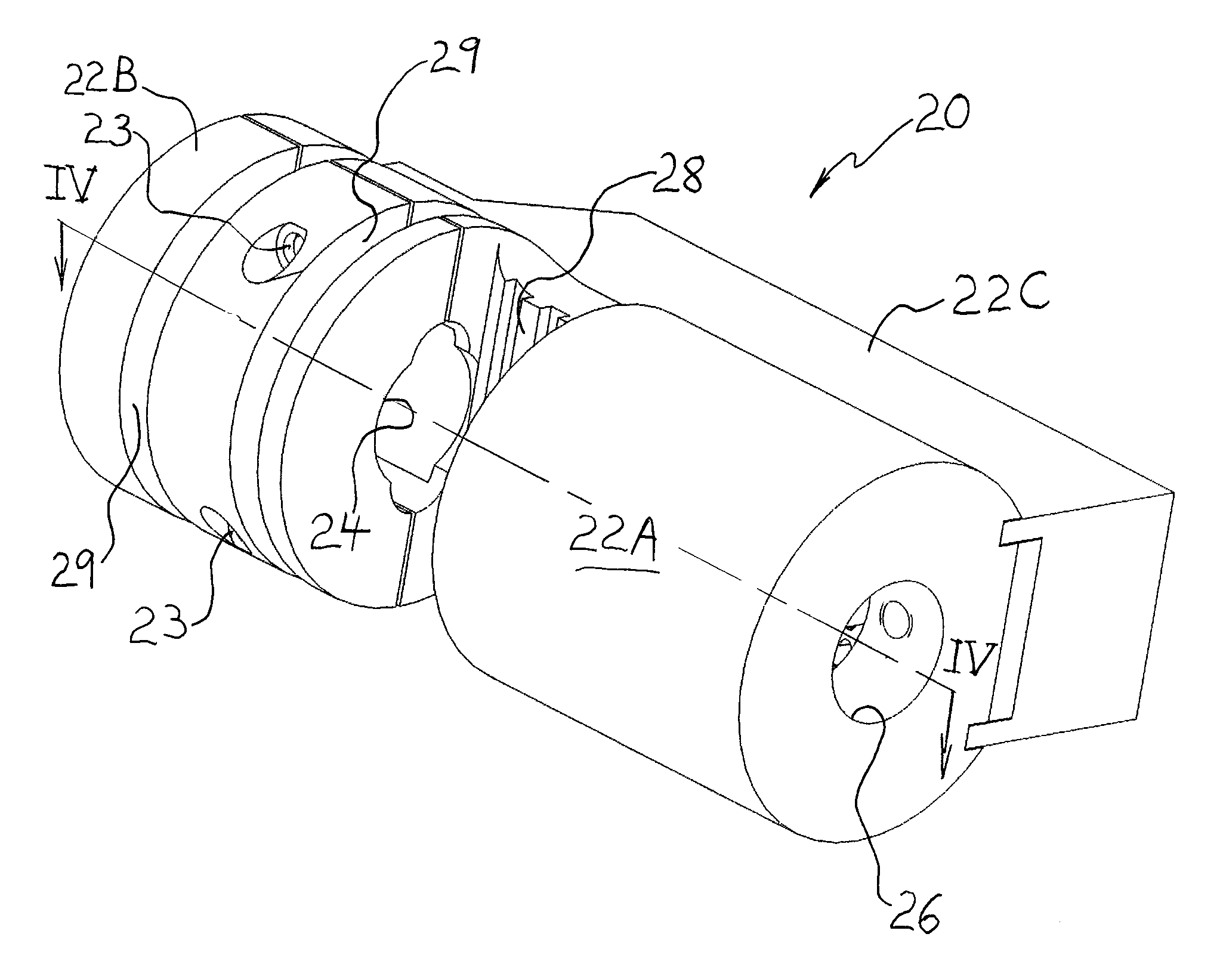
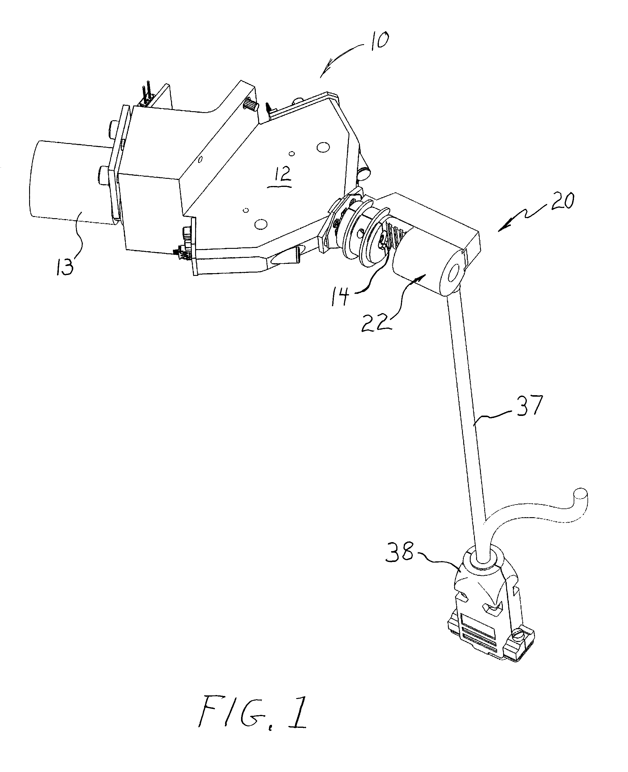
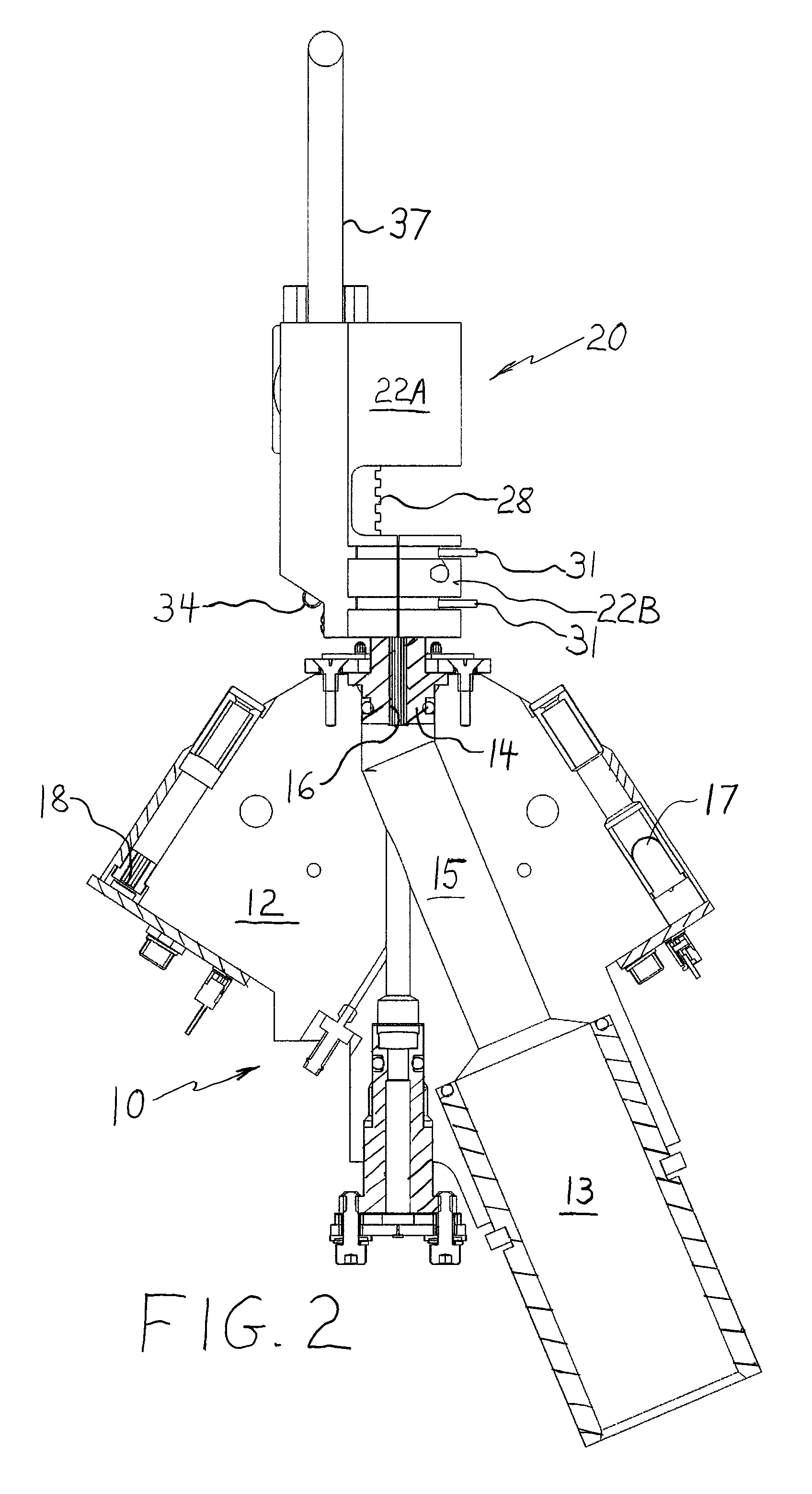
[0025]FIGS. 1-4 illustrate the present invention. In FIG. 1, a non-contact tonometer (“NCT”) is identified generally by reference numeral 10. NCT 10 is operable to measure intraocular pressure of an eye by discharging an air pulse at the eye to applanate a cornea of the eye. For this purpose, NCT 10 includes a measurement head 12 and a nosepiece 14 carried by the measurement head, wherein the nosepiece includes a fluid discharge passage 16 for discharging the air pulse along a test axis at the cornea. The air pulse may be generated by a pump mechanism (not shown) communicating with a plenum 13, and the air pulse is conveyed through a conduit 15 in measurement head 12 to discharge passage 16. Discharge passage 16 defines the test axis along which the fluid pulse travels toward the cornea, and may be a passage formed directly within nosepiece 14 or may be formed by a thin tube embedded or fixed in the nosepiece. As will be readily understood by those skilled in the art of non-contact ...

second embodiment

[0033]FIGS. 5-8 show a tonometer calibration tool 40 formed in accordance with the present invention. Calibration tool 40 comprises a body 42 configured to be directly and removably mounted on measurement head 12 of NCT 10 instead of nosepiece 14. More specifically, body 42 includes a mating feature in the form of a pair of mounting pins 44A, 44B sized for receipt by a corresponding pair of mounting holes 19A, 19B in measurement head 12. One of the mounting pins may be hexagonal (see mounting pin 44B in FIG. 7) to facilitate insertion of mounting pins 44A, 44B into mounting holes 19A, 19B.

[0034]Body 42 includes a sensor portion 41 for housing pressure sensor 30 and emitter 34. In the embodiment shown, sensor portion 41 includes a sensor block 42A and a support member 42D. Body 42 also includes a mounting block 42B from which the pair of mounting pins 44A, 44B extend and a bridge member 42C connecting sensor portion 41 to mounting block 42B. Sensor block 42A may be fixed to bridge me...


PUM

PropertyMeasurementUnit
intraocular pressureaaaaaaaaaa
pressureaaaaaaaaaa
noiseaaaaaaaaaa

Abstract

A tool for calibrating a non-contact tonometer (NCT) comprises a body having a mating feature configured for removably mounting the body on the nosepiece or on the measurement head of the NCT, a pressure sensor carried by the body and arranged to receive an air pulse discharged by the NCT to provide a pressure signal in response to the air pulse, and a radiation emitter carried by the body, wherein the radiation emitter provides a pseudo-applanation event when the pressure signal reaches a predetermined level that is detectable by the NCT as though an actual corneal applanation had taken place. In one embodiment, the mating feature includes a mounting orifice for receiving a portion of the nosepiece. In another embodiment, the mating feature includes a pair of mounting pins sized for receipt by a corresponding pair of mounting holes in the measurement head of the NCT.

Description

FIELD OF THE INVENTION[0001]The present invention relates generally to non-contact tonometers that measure intraocular pressure (IOP) by directing a fluid pulse at the cornea, and more particularly to a tool for calibrating such non-contact tonometers.BACKGROUND OF THE INVENTION[0002]Existing non-contact tonometers measure IOP by activating a pump mechanism to fire an air pulse at the cornea to flatten or “applanate” a predetermined area of the cornea, detecting corneal applanation caused by the air pulse and a plenum pressure of the pump mechanism, and correlating the plenum pressure at the moment of applanation with IOP. In older instruments, the time elapsed to achieve applanation was correlated to IOP as an indirect representation of plenum pressure based on a linearly increasing pressure profile in the plenum. In present day instruments, a pressure sensor is mounted in the plenum for providing a signal proportional to the plenum pressure. Regardless of whether elapsed time or a...

Claims


Application Information

Patent Timeline
Patent Type & Authority Patents(United States)
IPC IPC(8): G01L27/00
CPCA61B3/165G01L27/002
Inventor BONAVENTURA, RUSSELLKELKENBERG, DAVID G.BEVERLY, DAVID L.MILLER, DONALD E.LUCE, DAVID A.
Owner REICHERT
Why Eureka
Try Eureka