
Thimble for cyclone separator

Active Publication Date: 2019-08-22
FOSBEL WAHL HLDG LLC
View PDF0 Cites 1 Cited by
  • Summary
  • Abstract
  • Description
  • Claims
  • Application Information

AI Technical Summary

Benefits of technology

The invention is a thimble assembly for a cyclone separator that can be used on different types of cyclone units. This design allows manufacturers to produce parts in large quantities and keep them on hand, reducing lead times and the need for custom parts. The thimble assembly is flexible and can be easily adapted for different installations, without the need for confirming the size of the unit beforehand. This saves time and engineering effort.

Problems solved by technology

Cyclone separators such as used in cement making plants operate at very high temperature, approaching 1000 degrees C. for example, and are exposed to corrosive materials.
These harsh environments can degrade the thimble to a condition requiring its replacement long before the end of the working life of the cyclone separator.
Replacement of a thimble has been an expensive proposition in part because a new premium thimble will typically be custom built for a specific installation.
This field study adds to basic costs and extends the delivery time of a replacement thimble.
The aftermarket industry has generally not found it practical to build and inventory complete thimble units because of the variety of separator sizes in installed plants.
Cyclone separators operating at high temperature and subjected to corrosive materials have been susceptible to early thimble degradation in part, because of relatively large exposed metal areas.
Prior thimble designs have been relatively expensive to manufacture, for example, because segments making up the circular thimbles were made with arcuate shapes that complicated their tooling, molding, and assembly.

Method used


Image

  • Thimble for cyclone separator
  • Thimble for cyclone separator
  • Thimble for cyclone separator

Examples


Embodiment Construction

[0038]As used herein, when a range such as 5 to 25 (or 5-25) is given, this means preferably at least 5, and separately and independently, preferably not more than 25.

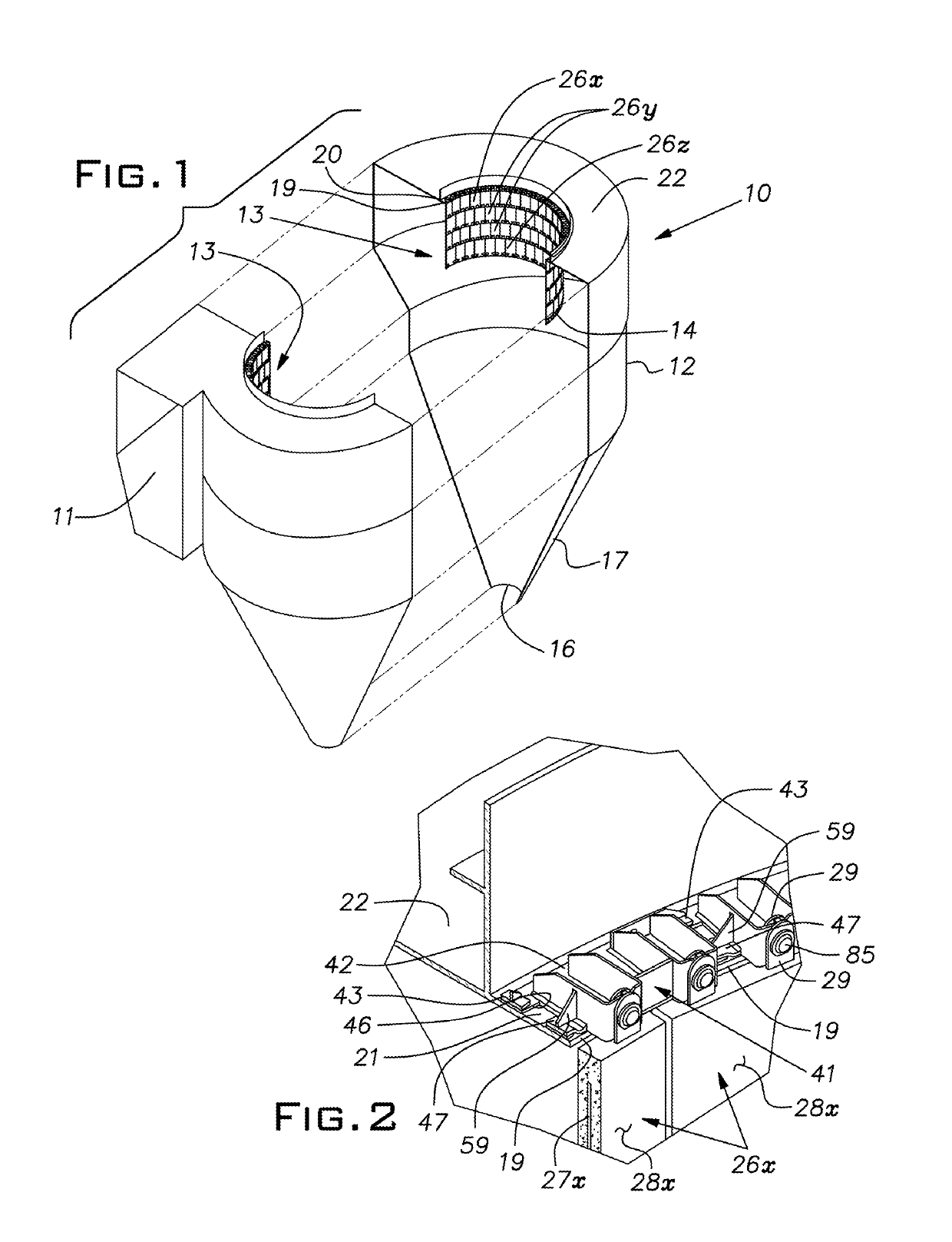
[0039]FIG. 1 illustrates a cyclone separator 10 of a type that is used, for example, in a lower hot stage of a cement manufacturing plant. A mixed phase of gases and solid particulate matter enters an inlet 11 of a housing 12. In the housing 12, the mixture swirls around a central thimble or thimble assembly 13. Gases enter a lower open end 14 of the thimble 13, pass vertically upwardly through the interior of the thimble and exit the housing 12. Particulate matter descends in the housing 12 and exits through an outlet 16 in a conical bottom part 17 of the housing 12.

[0040]The thimble assembly 13 is concentric with a perimeter of an exhaust opening 19 defining an inside diameter bounded by a shelf 21 formed by an upper wall 22 of the housing 12.

[0041]The shelf opening diameter of existing cyclone separators of the type...


PUM

PropertyMeasurementUnit
Lengthaaaaaaaaaa
Angleaaaaaaaaaa
Angleaaaaaaaaaa

Abstract

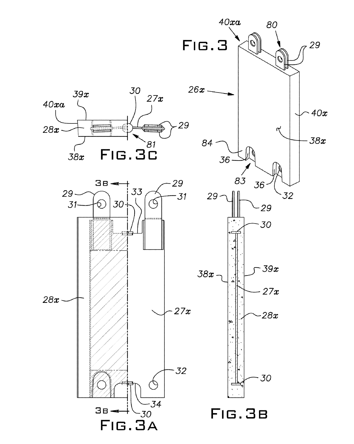
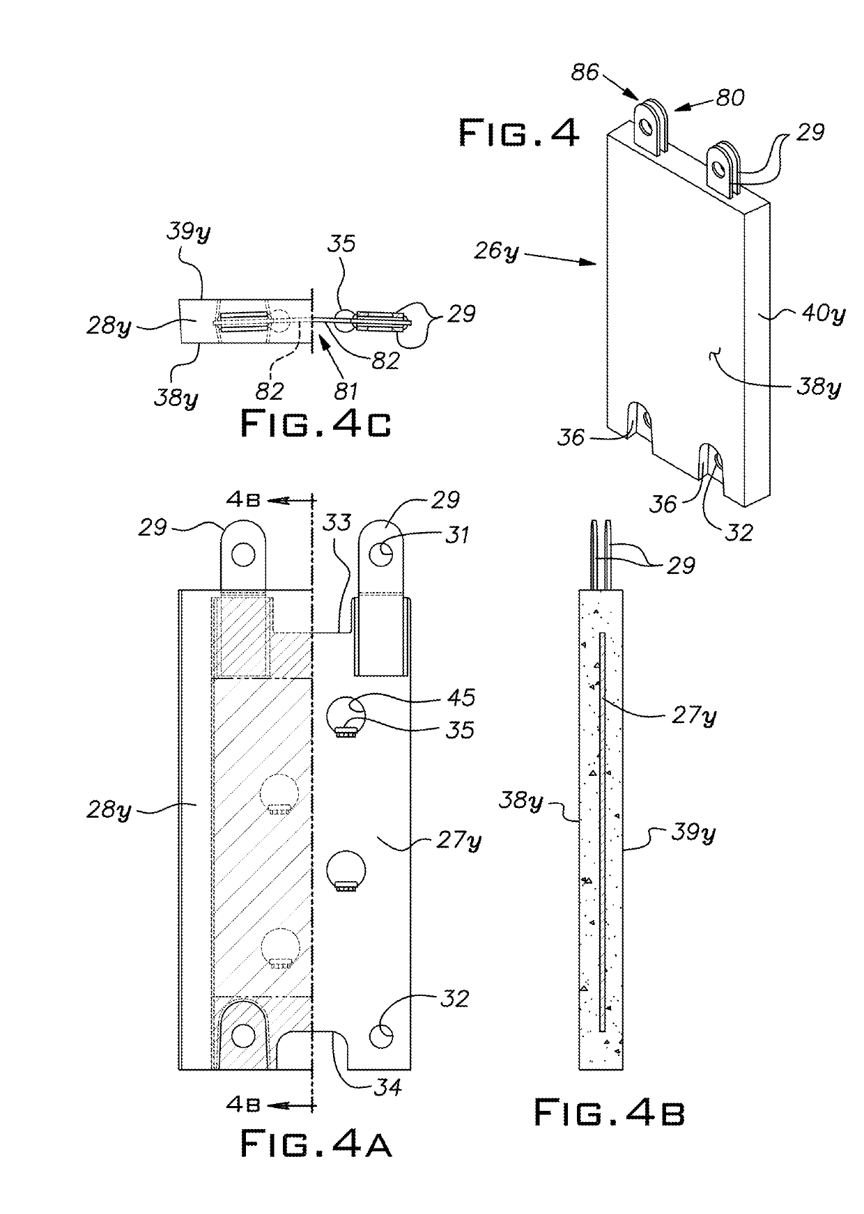
A thimble assembly for a cyclone separator comprising a plurality of mounting brackets separately mountable on a shelf of the separator along the perimeter of an exhaust opening, a plurality of segments vertically successively suspended from the brackets, the segments of an upper row being joined to the brackets, the segments of each successive lower row being joined to the segments of a row immediately above, each bracket exclusively serving a chord of an arc concentric with the preferably circular opening that is substantially the same in length as the chord of an arc that a segment spans, a center-to-center chordal spacing of adjacent brackets being the same as a center-to-center distance of an adjacent pair of segments.

Description

The present invention relates to a thimble assembly for a cyclone separator particularly useful in high temperature, corrosive atmospheres.BACKGROUND OF THE INVENTION[0001]Cyclone separators are used in different applications where solid particulates suspended in a gas phase are to be separated from the gas phase. A separator typically comprises a cyclone housing having an upper substantially cylindrical part with an upwardly extending circular discharge for the gas phase, a lower conical part having an outlet at its narrow bottom for discharging particulate matter, a tangential inlet in the upper part for introducing the suspension which is to be separated, and a central circular structure called a thimble depending from a shelf at an upper wall of the housing. The thimble (which can also be referred to as a central tube, a vortex finder or a dip tube) is adjacent the outlet and extends from the shelf axially in the cyclone housing to a distal free open end. The thimble forces the ...

Claims


Application Information

Patent Timeline
IPC IPC(8): B04C5/13B04C5/081B01D21/00B01D45/16F16B2/06F16M13/02F27B7/20
CPCB04C5/13B04C5/081B01D21/0087B01D45/16F16B2/065F16M13/022F27B7/2016F16B2001/0035F16B47/00F16M13/02F16B2200/50F16B2200/503F16B2200/506F16B2200/83
Inventor MERCIER, GILLESCHERICO, STEPHEN D.UPP, TIMOTHY A.
Owner FOSBEL WAHL HLDG LLC
Learn More