Joint for connecting workpieces

a workpiece and joint technology, applied in the direction of couplings, manufacturing tools, rotary cutting tools, etc., can solve the problem of limited application and achieve the effect of reducing adhesive curing time and increasing productivity

Inactive Publication Date: 2006-12-07
CASTO DANIEL A
View PDF29 Cites 57 Cited by
  • Summary
  • Abstract
  • Description
  • Claims
  • Application Information

AI Technical Summary

Benefits of technology

[0008] Therefore, it is an object of the invention to provide a joint that increases productivity by providin...

Problems solved by technology

One disadvantage of the dovetail joint is that its applic...

Method used


Image

  • Joint for connecting workpieces
  • Joint for connecting workpieces
  • Joint for connecting workpieces

Examples


Embodiment Construction

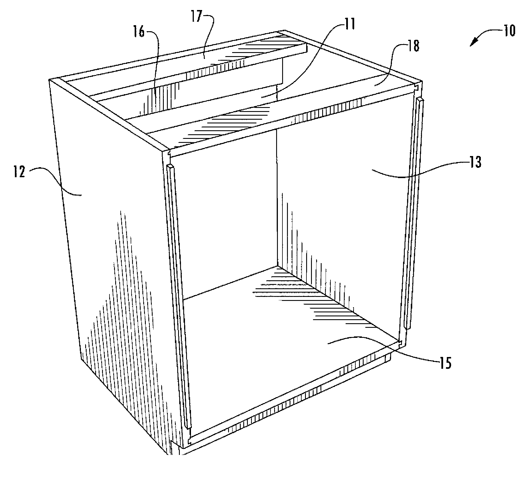
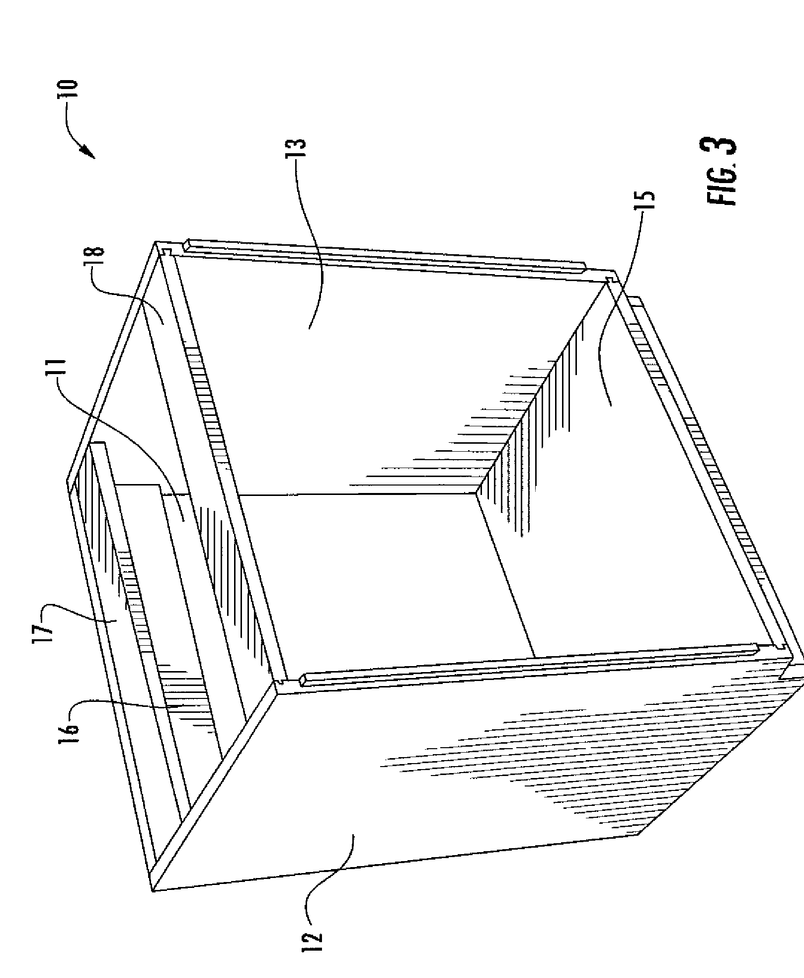
[0054] Referring now specifically to the drawings, a joint for securing workpieces together according to an embodiment of the invention is illustrated in FIG. 10 and shown generally at reference numeral 30. The joint 30 includes an outwardly extending projection 31 positioned on a first workpiece 32 and a complementary slot 33 for receiving the projection 31 on a second workpiece 34.

[0055] As shown in FIG. 11, the projection 31 includes a pair of generally convex opposing sidewalls 36 and 37 and an end wall 38. The sidewalls 36 and 37 each include two angled sidewall segments 36A, 36B and 37A, 37B. As illustrated, the sidewall segments 36A and 37A project from the first workpiece 32 at an angle outwardly away from a centerline of the workpiece 32, and the sidewall segments 36B and 37B extend from the distal ends of the sidewall segments 36A and 37A to the end wall 38 at an angle inwardly towards the centerline of the workpiece 32, thereby forming the generally convex profile of the...


PUM

PropertyMeasurementUnit
Widthaaaaaaaaaa

Abstract

A joint for securing two workpieces together. The joint includes a projection and a complimentary slot for receiving and securing the projection therein. The projection includes spaced-apart convex sidewalls extending outwardly from a first workpiece, and an end wall connecting outer ends of the sidewalls. The slot is formed in a second workpiece, and includes an opening for receiving the projection therethrough and a pair of spaced-apart concave sidewalls which define lateral boundaries of the slot.

Description

[0001] This application claims the benefit of Provisional Application No. 60 / 682,100 filed on May 18, 2005.TECHNICAL FIELD AND BACKGROUND OF THE INVENTION [0002] The present invention relates to a joint for securing workpieces together. In particular, the invention relates to a joint for securing workpieces together without the use of a clamp, fastener, or adhesive. [0003] Joints for securing workpieces together take many forms. Some of the typical joints used are dovetail joints, FIG. 1, and dado joints, FIG. 2. Dovetail joints may be formed by cutting a plurality of slots into adjacent workpieces to form outwardly projecting fingers, as shown in FIG. 1, or by cutting a single slot on one workpiece and a single outwardly projecting finger on another. One disadvantage of the dovetail joint is that its application can be limited due to the method of assembling the joint. To assemble the joint, the outwardly projecting finger must be slid into the complimentary slot. Thus, a specific ...

Claims


Application Information

Patent Timeline
IPC IPC(8): F16D1/00
CPCB27G13/002B27G13/14Y10T403/7094Y10T409/303808F16B12/125F16B2200/30
Inventor CASTO, DANIEL A.
Owner CASTO DANIEL A
Why Eureka
Try Eureka