
Radiographic apparatus and radiation detection signal processing method

Inactive Publication Date: 2007-02-15
SHIMADZU CORP
View PDF14 Cites 1 Cited by
  • Summary
  • Abstract
  • Description
  • Claims
  • Application Information

AI Technical Summary

Benefits of technology

[0010] This invention has been made having regard to the state of the art noted above, and its object is to provide a radiographic apparatus and a radiation detection signal processing method for eliminating lag-behind parts from radiation detection signals in a simple way.
[0012] With the radiographic apparatus according to this invention, the lag correcting device performs a lag correction of a lag-behind part by eliminating the lag-behind part from a radiation detection signal, and the non-irradiation signal acquiring device acquires a plurality of radiation detection signals in time of non-irradiation before irradiation of the radiation in an imaging event. The lag image acquiring device acquires a lag image based on the radiation detection signals acquired by the non-irradiation signal acquiring device. The lag correcting device performs the lag correction by subtracting the lag image acquired by the lag image acquiring device from a radiographic image serving the intended purpose. Thus, there is no need to carry out a lag correction by performing recursive computations the number of times radiation detection signals are sampled, as described in Japanese Unexamined Patent Publication No. 2004-242741 noted hereinbefore. A lag-behind part may be eliminated from a radiation detection signal in a simple way. Further, there is no need to use backlight as used in Japanese Unexamined Patent Publication No. H9-9153 noted hereinbefore. This avoids complication of the apparatus construction.
[0017] Thus, a plurality of radiation detection signals are acquired in time of non-irradiation after lapse of the predetermined time from the irradiation in the preceding imaging event. Consequently, a plurality of radiation detection signals are acquired in time of non-irradiation before irradiation in the current imaging event. A signal may be acquired in a state of including only the long time constant components which remain after lapse of the predetermined time. The signal is free from the short and medium time constant components, and a lag-behind part having the long time constant components may be eliminated accurately.
[0026] In this example, whenever a radiation detection signal is acquired in time of non-irradiation, the recursive computation is repeated based on the latest radiation detection signal acquired, and the lag image resulting from a plurality of radiation detection signals successively acquired in the past. The lag image ultimately obtained is a goal image used as the basis for the lag correction. Only the newest lag image obtained by recursive computation and the lag image (i.e. the lag image used as the basis of the recursive computation) before the newest lag image may be retained, with the other lag images (i.e. the lag images earlier than the above two lag images) discarded. Then, only the two images may be retained, which provides an advantage of simplifying the construction.
[0027] One example of recursive computation is a recursive weighted average. With the lag image acquired from the weighted average, the lag correction may be carried out with increased reliability.

Problems solved by technology

Particularly, in a fluoroscopy that performs X-ray irradiation continually at short time intervals (e.g. 1 / 30 second), time lags of the lag-behind parts have influences serious enough to hinder diagnosis.
Particularly where backlight is used in an FPD having a lightweight construction, the construction must become heavy and complicated again.
This renders the lag correction complicated and cumbersome.

Method used


Image

  • Radiographic apparatus and radiation detection signal processing method
  • Radiographic apparatus and radiation detection signal processing method
  • Radiographic apparatus and radiation detection signal processing method

Examples


first embodiment

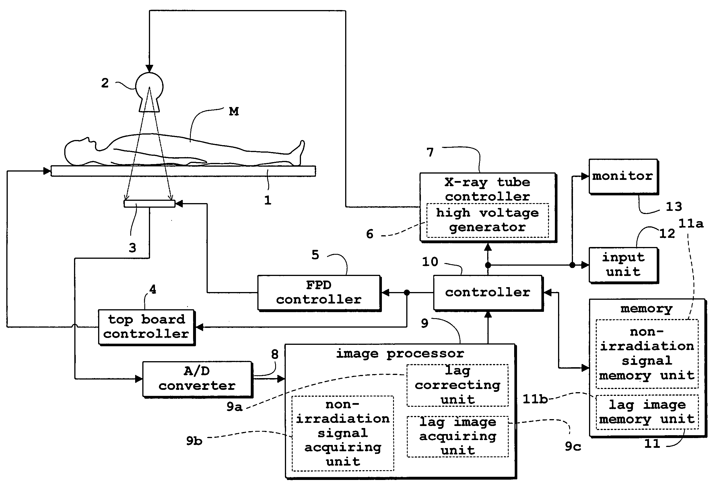
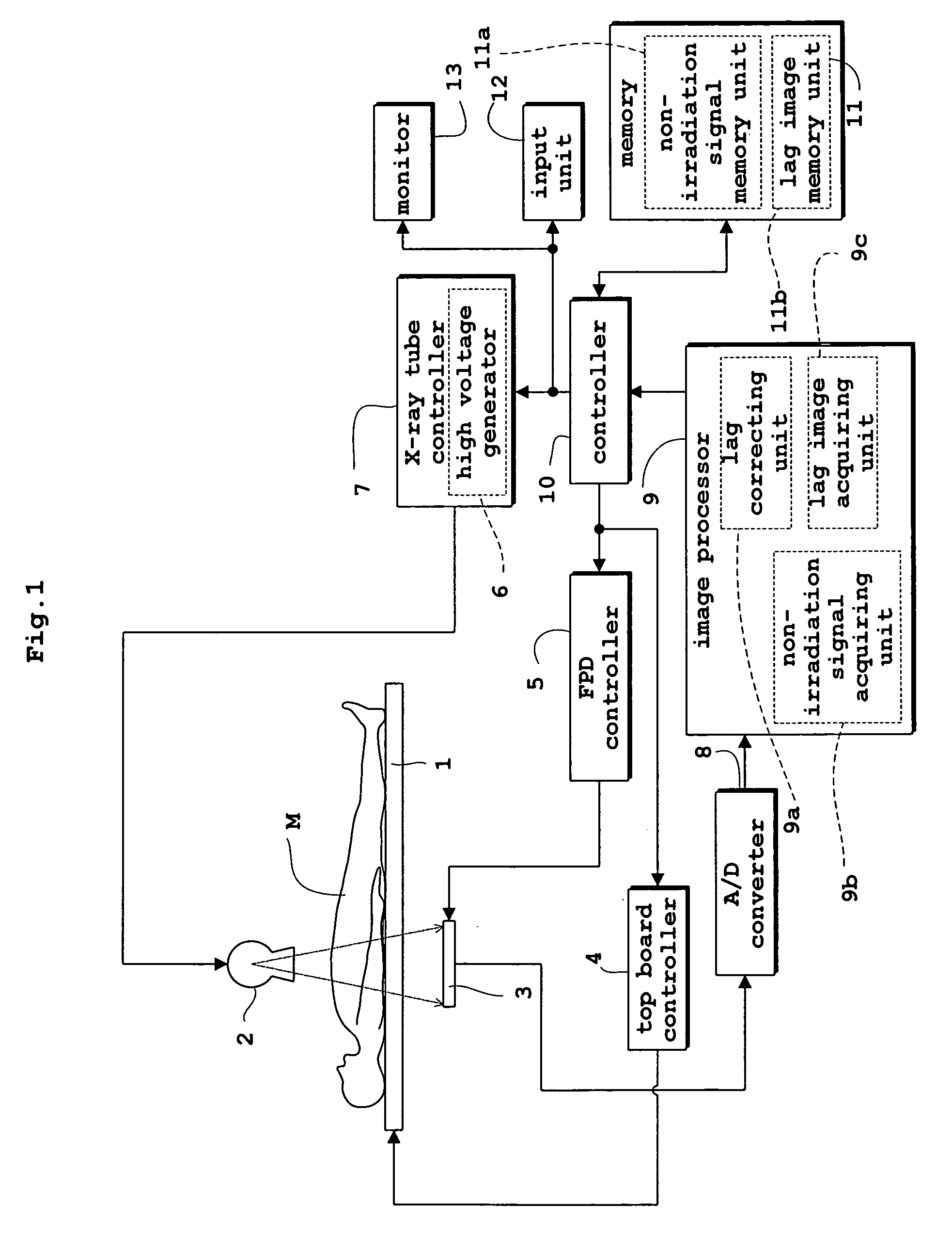
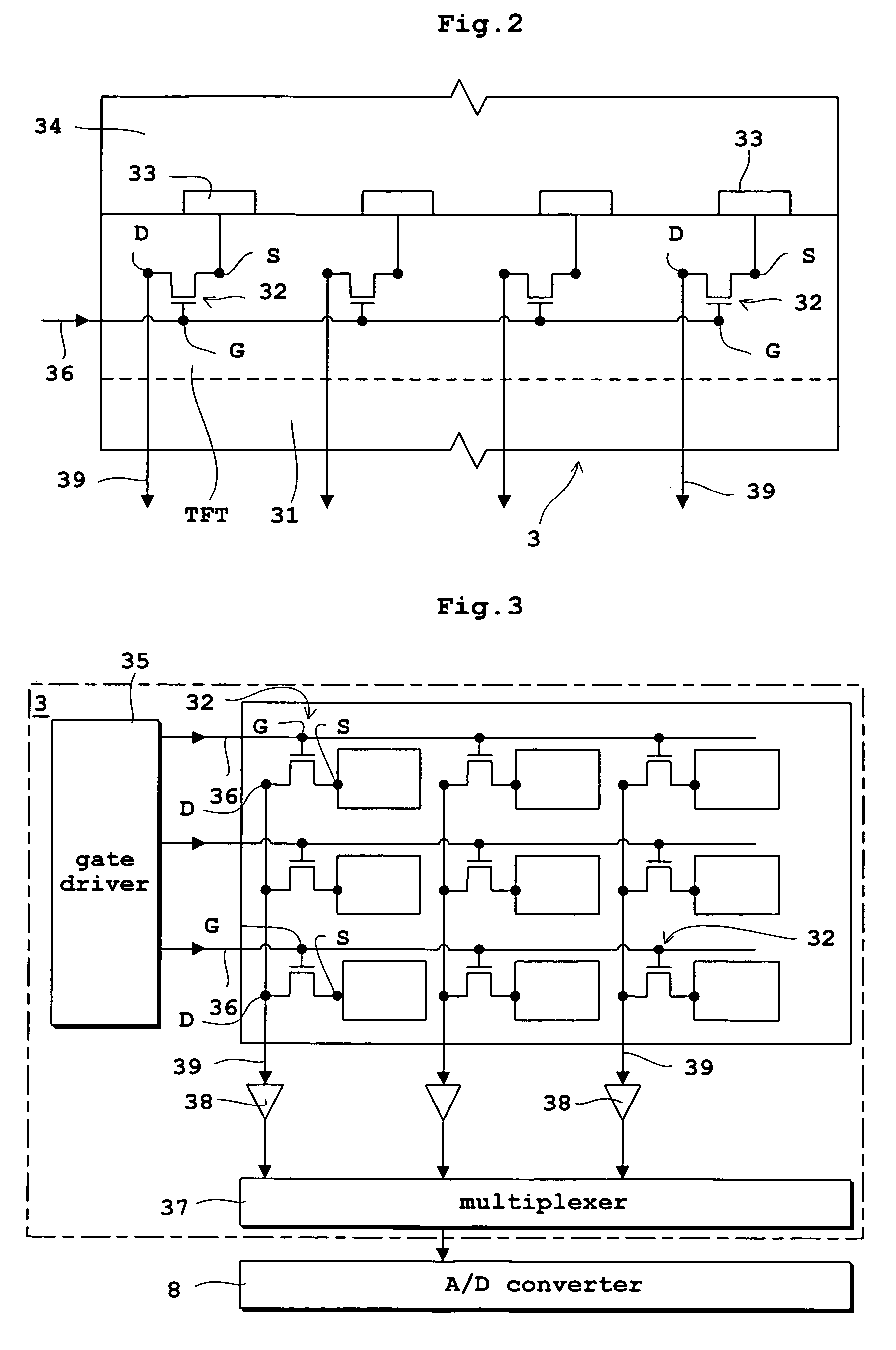
[0043]FIG. 1 is a block diagram of a fluoroscopic apparatus in the first embodiment. FIG. 2 is an equivalent circuit, seen in side view, of a flat panel X-ray detector used in the fluoroscopic apparatus. FIG. 3 is an equivalent circuit, seen in plan view, of the flat panel X-ray detector. The first embodiment, and also the second and third embodiments to follow, will be described, taking the flat panel X-ray detector (hereinafter called “FPD” as appropriate) as an example of radiation detection device, and the fluoroscopic apparatus as an example of radiographic apparatus.

[0044] As shown in FIG. 1, the fluoroscopic apparatus in the first embodiment includes a top board 1 for supporting a patient M, an X-ray tube 2 for emitting X rays toward the patient M, and an FPD 3 for detecting X rays transmitted through the patient M. The X-ray tube 2 corresponds to the radiation emitting device in this invention. The FPD 3 corresponds to the radiation detecting device in this invention.

[0045...

second embodiment

[0077] Next, the second embodiment of this invention will be described with reference to the drawings.

[0078] Like reference signs will be used to identify like parts which are the same as in the first embodiment and will not be described again. A fluoroscopic apparatus in the second embodiment is similar to the apparatus in the first embodiment, and only the series of signal processing by the lag correcting unit 9a, non-irradiation signal acquiring unit 9b and lag image acquiring unit 9c is different from that in the first embodiment.

[0079] The series of signal processing by the lag correcting unit 9a, non-irradiation signal acquiring unit 9b and lag image acquiring unit 9c in the second embodiment will be described with reference to the flow chart of FIG. 7. Like numerals are affixed to like steps in the first embodiment and will not be described again.

[0080] (Step S1) Waiting Time Elapsed?

[0081] As in the first embodiment, a checking is made whether or not the waiting time TW h...

third embodiment

[0093] Next, the third embodiment of this invention will be described with reference to the drawings.

[0094]FIG. 8 is a schematic view showing flows of data to and from an image processor and a memory in the third embodiment. Like reference signs will be used to identify like parts which are the same as in the first and second embodiments, and will not be described again. A fluoroscopic apparatus in the third embodiment is the same as the apparatus in the first and embodiments, except the flows of data to and from the image processor 9 and memory 11 shown in FIG. 8. The series of signal processing by the lag correcting unit 9a, non-irradiation signal acquiring unit 9b and lag image acquiring unit 9c also is different from those in the first and second embodiments.

[0095] In the third embodiment, as shown in FIG. 8, the lag image acquiring unit 9c acquires a lag image by recursive computation based on the X-ray detection signals in time of non-irradiation read from the non-irradiatio...


PUM


Abstract

When performing a lag correction of a lag-behind part by eliminating the lag-behind part from an X-ray detection signal obtained, a plurality of X-ray detection signals in time of non-irradiation before X-ray irradiation in an imaging event, and a lag image based on the X-ray detection signals acquired. The lag correction performed by subtracting the lag image acquired from the X-ray detection signal. Thus, the lag-behind part is eliminated from the X-ray detection signal in a simple way.

Description

BACKGROUND OF THE INVENTION [0001] (1) Field of the Invention [0002] This invention relates to a radiographic apparatus and a radiation detection signal processing method for obtaining radiographic images based on radiation detection signals resulting from radiation emitted to and transmitted through an object under examination. More particularly, the invention relates to a technique for eliminating lag-behind parts from the radiation detection signals. [0003] (2) Description of the Related Art [0004] An example of radiographic apparatus is an imaging apparatus that obtains X-ray images by detecting X rays. This apparatus used an image intensifier as an X-ray detecting device in the past. In recent years, a flat panel X-ray detector (hereinafter called simply “FPD”) has come to be used instead. [0005] The FPD has a sensitive film laminated on a substrate, detects radiation incident on the sensitive film, converts the detected radiation into electric charges, and stores the electric ...

Claims


Application Information

Patent Timeline
IPC IPC(8): H05G1/64
CPCA61B6/585A61B6/583A61B6/00
Inventor OKAMURA, SHOICHITANABE, KOICHI
Owner SHIMADZU CORP
Learn More