Contour crafting extrusion nozzles

a technology of extrusion nozzle and concentric molding, which is applied in the direction of auxillary shaping apparatus, butter manufacture, shaping building parts, etc., can solve the problems of waste of materials, small sized structures that may require the efforts of many workers, and construction can still be very labor-intensive, so as to achieve the effect of maximizing the height of the outl

Active Publication Date: 2014-08-12
UNIV OF SOUTHERN CALIFORNIA
View PDF25 Cites 20 Cited by
  • Summary
  • Abstract
  • Description
  • Claims
  • Application Information

AI Technical Summary

Benefits of technology

[0031]The controller may be configured to direct the nozzle positioning system to cause the second extrusion nozzle to move in synchronism with and behind the first extrusion nozzle. This may cause the second extrusion nozzle to extrude the substantially horizontal strip on the substantially vertical surface of the horizontal extruded layer extruded during the same horizontal traverse by the first extrusion nozzle.
[0048]The extrusion nozzle may include at least one spring configured to urge the two portions apart from one another so as to maximize the height of the outlet when no external force is applied between the two portions.

Problems solved by technology

Despite centuries of development, however, construction can still be very labor intensive.
Even a modest sized structure may require the efforts of numerous workers.
Construction may also waste material.
Construction may also be hazardous.
Construction workers may be killed or seriously injured.
These problems gave rise to the nozzle assemblies disclosed in U.S. Pat. No. 7,153,454, issued Dec. 26, 2006, entitled “Multi-Nozzle Assembly for Extrusion of Wall,” as well as the related equipment and methods disclosed in the patent applications cited above.
Such advancements have brought with them corresponding challenges.
For example, it may be challenging to extrude walls which have multiple layers, such as an internal core of insulation, a stucco exterior, and a plastered interior.
It may also be challenging to craft openings in such extruded walls for such components as windows and doors.
It may also be challenging to create a uniform and level base layer when the underlying surface is uneven.
This may cause a substantially horizontal strip of the construction material to be extruded from the extrusion nozzle onto the substantially vertical surface.

Method used


Image

  • Contour crafting extrusion nozzles
  • Contour crafting extrusion nozzles
  • Contour crafting extrusion nozzles

Examples


Embodiment Construction

[0072]Illustrative embodiments are now discussed. Other embodiments may be used in addition or instead. Details that may be apparent or unnecessary may be omitted to save space or for a more effective presentation. Conversely, some embodiments may be practiced without all of the details that are disclosed.

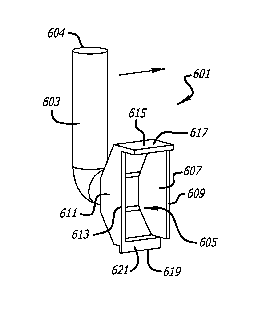
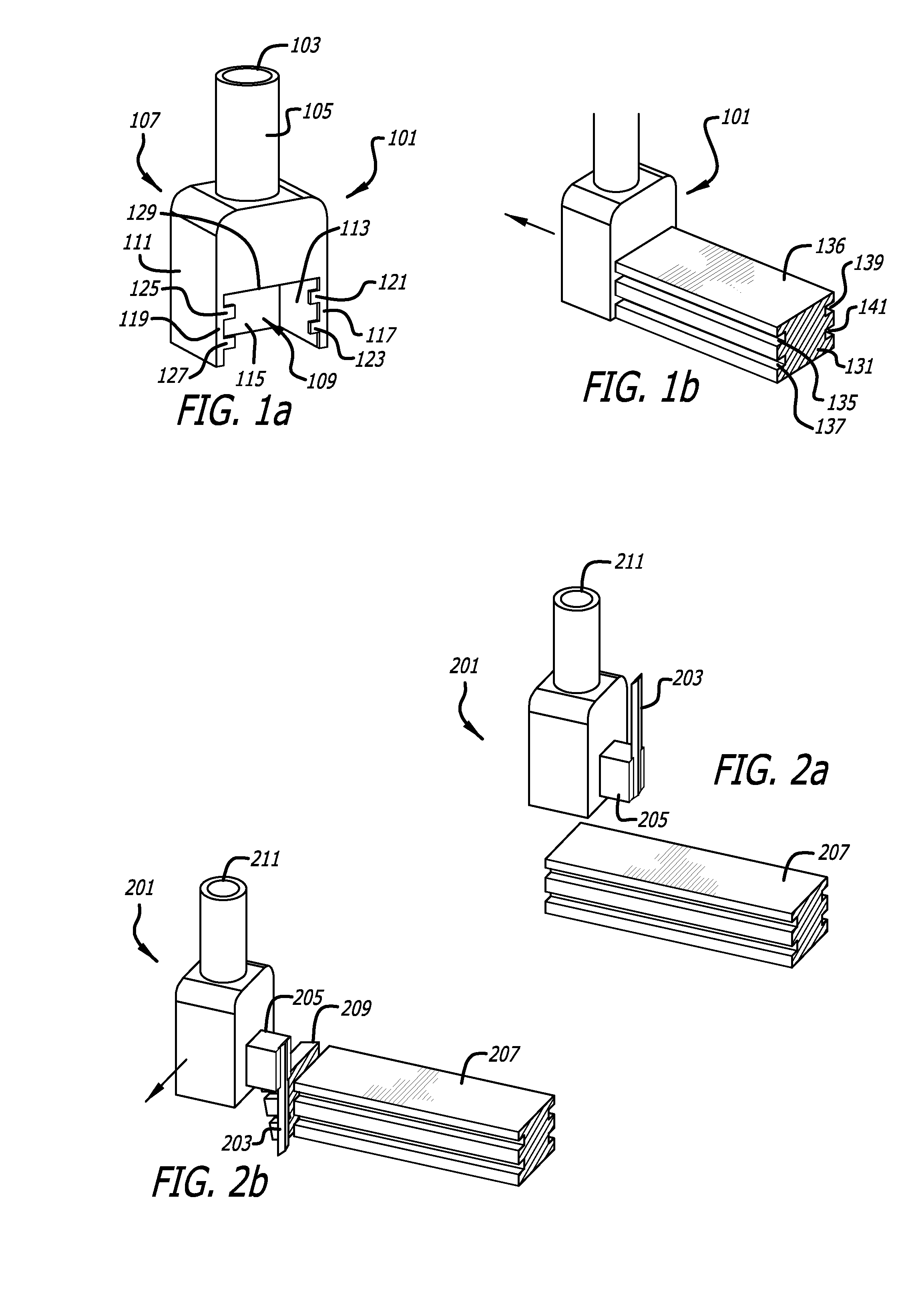
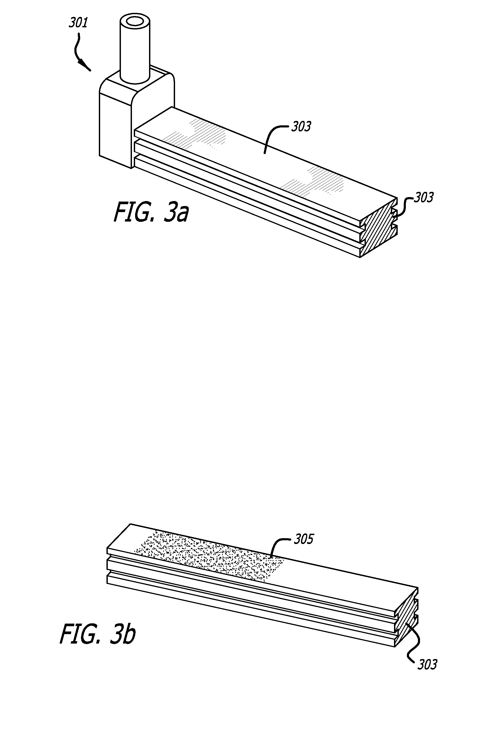
[0073]FIG. 1(a) illustrates an extrusion nozzle configured to extrude an internal extruded layer. An extrusion nozzle 101 may include an inlet 103, a tube 105, a housing 107 which has an outlet 109, side trowels 111 and 113, a rear wall 115, side trowels 117 and 119, and channel protrusions 121, 123, 125 and 127.

[0074]Construction material, such as cementitious material, foam, plaster, stucco, may be delivered in a viscous fluidic state into the inlet 103. This material may then be extruded through the outlet 109. The side trowels 117 and 119 may serve to shape the extrudate, along with the channel protrusions 121, 123, 125, and 127.

[0075]The construction material which is delivere...


PUM

PropertyMeasurementUnit
shapeaaaaaaaaaa
Viscous Fluid Flow Rateaaaaaaaaaa
lengthsaaaaaaaaaa

Abstract

An automated extrusion construction system may include an extrusion nozzle configured to extrude construction material in a substantially horizontal direction against an elongated and substantially vertical surface. An extrusion nozzle may have a height adjustment mechanism configured to adjust the height of an outlet in response to level deviations in the surface on which the construction material is extruded by the extrusion nozzle. An automated extrusion construction system may include a slicing mechanism configured to controllably slice through the extruded layer.

Description

CROSS-REFERENCE TO RELATED APPLICATION(S)[0001]This application is a U.S. National Phase filing of P.C.T. Application No. PCT / US2008 / 080976, entitled “Contour Crafting Extrusion Nozzles,” filed 23 Oct. 2008, which is based upon and claims priority to U.S. Provisional Patent Application Ser. No. 60 / 982,378, entitled “Nozzles for Contour Crafting of Walls,” filed Oct. 24, 2007, and U.S. Provisional Patent Application Ser. No. 60 / 990,581, filed Nov. 27, 2007, entitled “Methods for Sensing Viscous Fluid Flow Rate,”. The entire content of all three applications is incorporated herein by reference.[0002]This application is also a continuation-in-part application of the following:[0003]U.S. patent application Ser. No. 11 / 040,401, entitled “Robotic Systems for Automated Construction,”, filed Jan. 21, 2005 (issued Jan. 5, 2010 as U.S. Pat. No. 7,641,461); which claims priority to U.S. Provisional Application Ser. No. 60 / 537,756, entitled “Automated Construction Using Extrusion,”, filed Jan. ...

Claims


Application Information

Patent Timeline
Patent Type & Authority Patents(United States)
IPC IPC(8): B29C47/08E04G21/00B29C48/02B29C48/09B29C48/12B29C48/155B29C48/21B29C48/305B29C48/92
CPCB28B3/20B29C2947/926B29C47/0023B29C47/0066B29C2947/92571B29C47/026B29C47/14B29C2947/92514E04B1/16B29C47/003E06B1/04B32B7/00B29C2793/0027B29C47/92B29C47/065B28B11/04B29C47/0002E04B2/02E04B2/84B29C47/0038B29C47/0052B29C2947/92904E04B1/3505Y10T428/24992B29C48/09B29C48/0016B29C48/21B29C48/0022B29C48/92B29C48/155B29C48/001B29C48/02B29C48/12B29C2948/926B29C2948/92514B29C2948/92571B29C2948/92904E04G21/0463E04G2021/049B29C64/106B29C64/188B33Y10/00E04C1/00
Inventor KHOSHNEVIS, BEHROKH
Owner UNIV OF SOUTHERN CALIFORNIA
Why Eureka
Try Eureka