Supercharge Your Innovation With Domain-Expert AI Agents!

Image processing device and method for producing a restored image using a candidate point spread function

a technology of image processing and point spread, which is applied in the field of image processing device and method for restoring an image, and image capture device, which can solve the problems of image degraded, image may sometimes be added to image, blur of image, etc., and achieve the effect of reducing the amount of computation and the amount of memory spa

Active Publication Date: 2014-08-12
DOLBY INT AB
View PDF15 Cites 1 Cited by
  • Summary
  • Abstract
  • Description
  • Claims
  • Application Information

AI Technical Summary

Benefits of technology

This approach significantly reduces the amount of computation and memory required for PSF estimation and restoration, allowing for accurate image restoration with reduced computational resources and minimizing errors caused by noise or subject blur.

Problems solved by technology

In the case of capturing an image by a digital camera, noise may sometimes be added to the image due to the characteristics of a CCD (Charge-Coupled Device) or a readout circuit for CMOS or the characteristics of transmission paths.
Also, blur of an image due to an out-of-focus condition in capturing of the image or blur of an image due to camera shake occurs.
In this way, the captured image has blur which is attributed to user's handling of the camera in photographing in addition to the noise which is attributed to the specific characteristics of the captured image, so that the image is degraded.
However, increasing the sensitivity disadvantageously leads to amplification of noise.
As a result, a signal is buried in the noise so that, in many cases, large part of a resultant image is formed by the noise.
On the other hand, extending the exposure time enables accumulation of a larger amount of light which occurs at that site, resulting in an image which includes smaller noise.
In this case, a signal would not be buried in the noise, but there is a problem of generation of motion blur in an image due to camera shake.

Method used


Image

  • Image processing device and method for producing a restored image using a candidate point spread function
  • Image processing device and method for producing a restored image using a candidate point spread function
  • Image processing device and method for producing a restored image using a candidate point spread function

Examples


embodiment 1

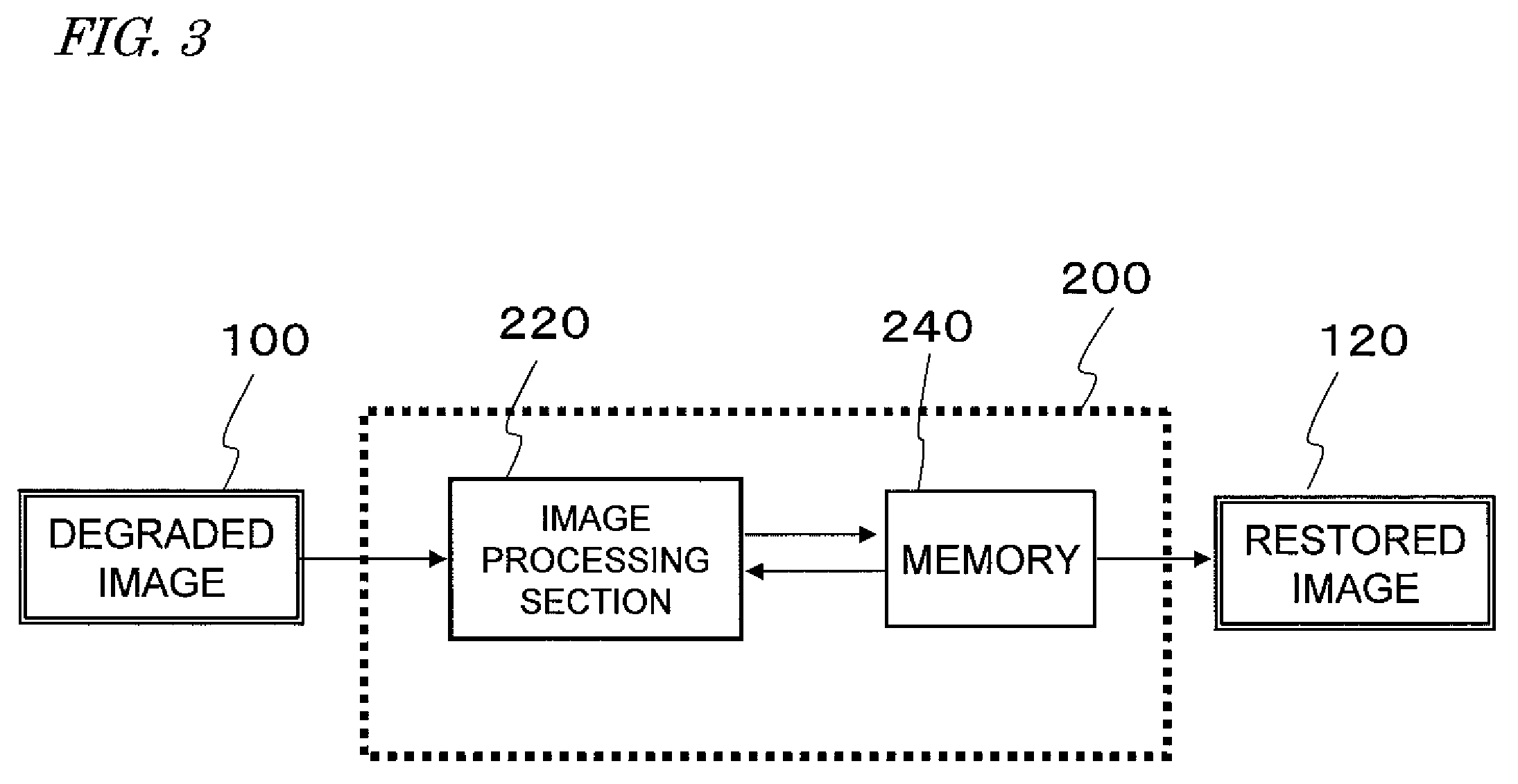
[0060]FIG. 3 is a diagram showing a general configuration of an image processing device 200 in the first embodiment of the present invention. The image processing device 200 of the present embodiment repeatedly performs a restoration process based on an input degraded image 100 to produce a restored image 120 that is close to an ideal image. The image processing device 200 includes an image processing section 220 for performing signal processing based on the input degraded image 100 and a memory 240 for storing various data generated in the course of the processing.

[0061]The degraded image 100 is data of an image photographed by an image capture device, such as a digital still camera, and includes motion blur which is attributed to camera shake. The image processing section 220 performs a restoration process of the degraded image 100 as well as various signal processing, such as color tone correction, change of resolution, and data compression. The image processing section 220 is pr...

embodiment 2

[0095]Next, the second embodiment of the present invention is described with reference to FIG. 8. The image processing device of the present embodiment is different from the image processing device of Embodiment 1 only in the method of selecting the candidate PSF in the PSF selection section 230, and the other features are common among Embodiments 1 and 2. Therefore, the features which are common among the image processing device of the present embodiment and the image processing device of Embodiment 1 are not described in this section, while only the differences are described.

[0096]The difference between the image processing device of the present embodiment and the image processing device of Embodiment 1 is that, in step S512 of FIG. 5, the image blocks for evaluation are selected not only from the degraded image but also from the provisional restored image. In step S508 shown in FIG. 5, the PSF estimation section 228 obtains fk (k=1, 2, . . . , K) for each of the image block pairs...

embodiment 3

[0102]Next, the third embodiment of the present invention is described. The image processing device of the present embodiment is different from the image processing devices of Embodiments 1 and 2 only in the method of selecting the candidate PSF in the PSF selection section 230, and the other features are common among Embodiments 1 to 3. Therefore, the features which are common among the image processing device of the present embodiment and the image processing devices of Embodiments 1 and 2 are not described in this section, while only the differences are described.

[0103]The different between the image processing device of the present embodiment and the image processing device of Embodiment 1 is that, in step S512 of FIG. 5, the image blocks for evaluation are selected not only from the degraded image but also from the provisional restored image. In the present embodiment, in step S512 of FIG. 5, the PSF selection section 230 sorts a plurality of estimated PSFs into a plurality of ...


PUM


Abstract

An image processing device extracts, in an image block selection section 226, a plurality of image block pairs from a degraded image and a provisional restored image, each of the image block pairs being formed by two image blocks at identical coordinates in the degraded image and the provisional restored image, and estimates a point spread function (PSF) for each of the image block pairs. From among the estimated PSFs, a PSF which is estimated to be close to a true PSF is selected as a candidate PSF. The estimation of the PSF is carried out on a block-by-block basis, whereby the amount of computation required for the estimation of the PSF can be reduced. Also, the estimation method used is not disturbed by an image block which includes noise, and therefore, a PSF which is close to the true PSF can be estimated.

Description

TECHNICAL FIELD[0001]The present invention relates to an image processing device and method for restoring an image, and an image capture device which includes the image processing device.BACKGROUND ART[0002]In the case of capturing an image by a digital camera, noise may sometimes be added to the image due to the characteristics of a CCD (Charge-Coupled Device) or a readout circuit for CMOS or the characteristics of transmission paths. Also, blur of an image due to an out-of-focus condition in capturing of the image or blur of an image due to camera shake occurs. In this way, the captured image has blur which is attributed to user's handling of the camera in photographing in addition to the noise which is attributed to the specific characteristics of the captured image, so that the image is degraded. Among such “blur” types, blur of an image which is attributed to a motion of a camera during photographing (exposure) is herein referred to as “motion blur”, so that it is distinguishab...

Claims


Application Information

Patent Timeline
Patent Type & Authority Patents(United States)
IPC IPC(8): H04N5/228G06K9/36H04N23/40
CPCG06T5/003G06T2207/20201G06T5/73
Inventor ISHII, YASUNORIMONOBE, YUSUKE
Owner DOLBY INT AB
Features
  • R&D
  • Intellectual Property
  • Life Sciences
  • Materials
  • Tech Scout
  • Unparalleled Data Quality
  • Higher Quality Content
  • 60% Fewer Hallucinations
Learn More