Retractable toe guard

a toe guard and retraction technology, applied in the field of lifts, can solve the problems of further complicating matters, further increasing costs, and complicated excavation of pits, and achieve the effect of benefiting the ar

Inactive Publication Date: 2014-08-19
OTIS ELEVATOR CO
View PDF23 Cites 7 Cited by
  • Summary
  • Abstract
  • Description
  • Claims
  • Application Information

AI Technical Summary

Benefits of technology

[0011]Another aspect of the system of the invention is a toe guard which requires virtually no clearance and is automatically or manually retractable under the bottom surface of the elevator car. The combination of features in the elevator system of the invention allows for pitless installation and greatly benefits the art.

Problems solved by technology

Moreover, the deeper a pit is dug the more likely it becomes that the water table in the area will be reached which further complicates matters.
Where an elevator system is a retrofit in an existing structure, the excavating of a pit is complicated further and further increases expense.
Additionally, the pit takes up space that could be otherwise employed.
Digging is thus not specifically required for the pit itself but a portion of the basement is lost and the elevator car, in a conventional system, could not be lowered to the basement level.
This could occur if insufficient space were left in the pit to receive the toe guard in the event the car continued too far downwardly in the hoistway (an over limit condition).
The foregoing limitations have been consistent drawbacks of the elevator art.
In an era of ever increasing cost of space and construction, the art is in need of pitless elevator systems for both new construction and retrofit applications in existing structures.

Method used


Image

  • Retractable toe guard
  • Retractable toe guard
  • Retractable toe guard

Examples


Embodiment Construction

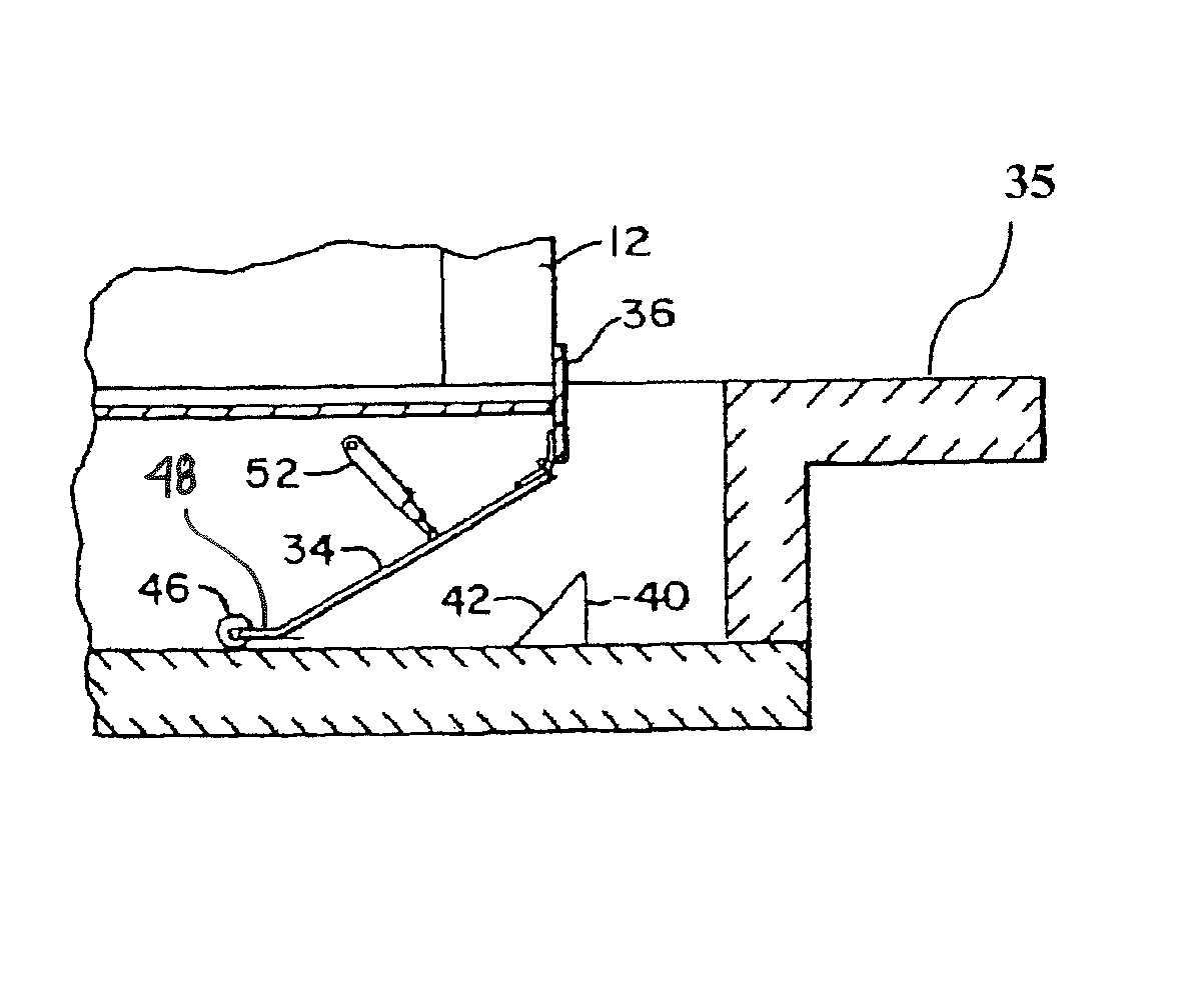
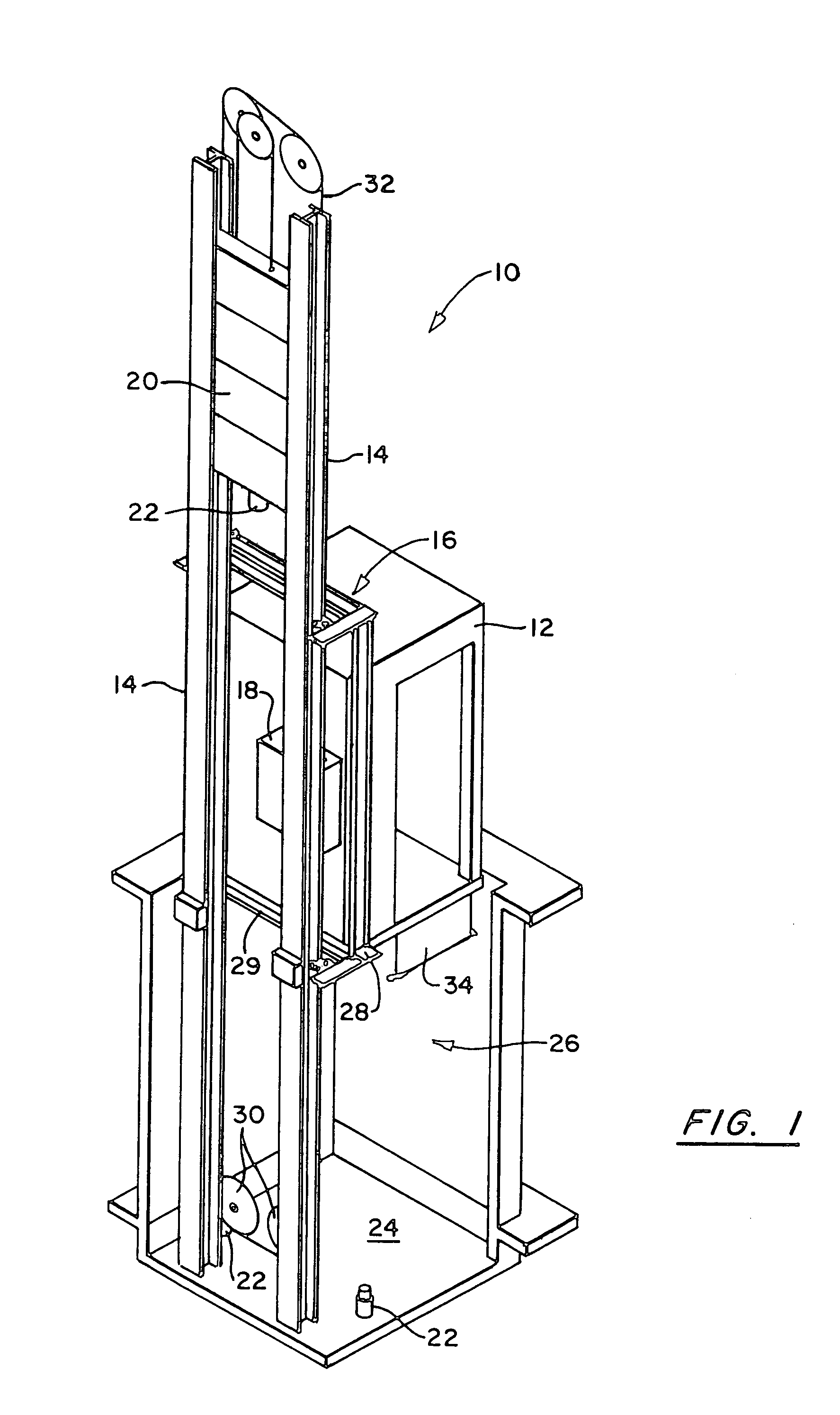
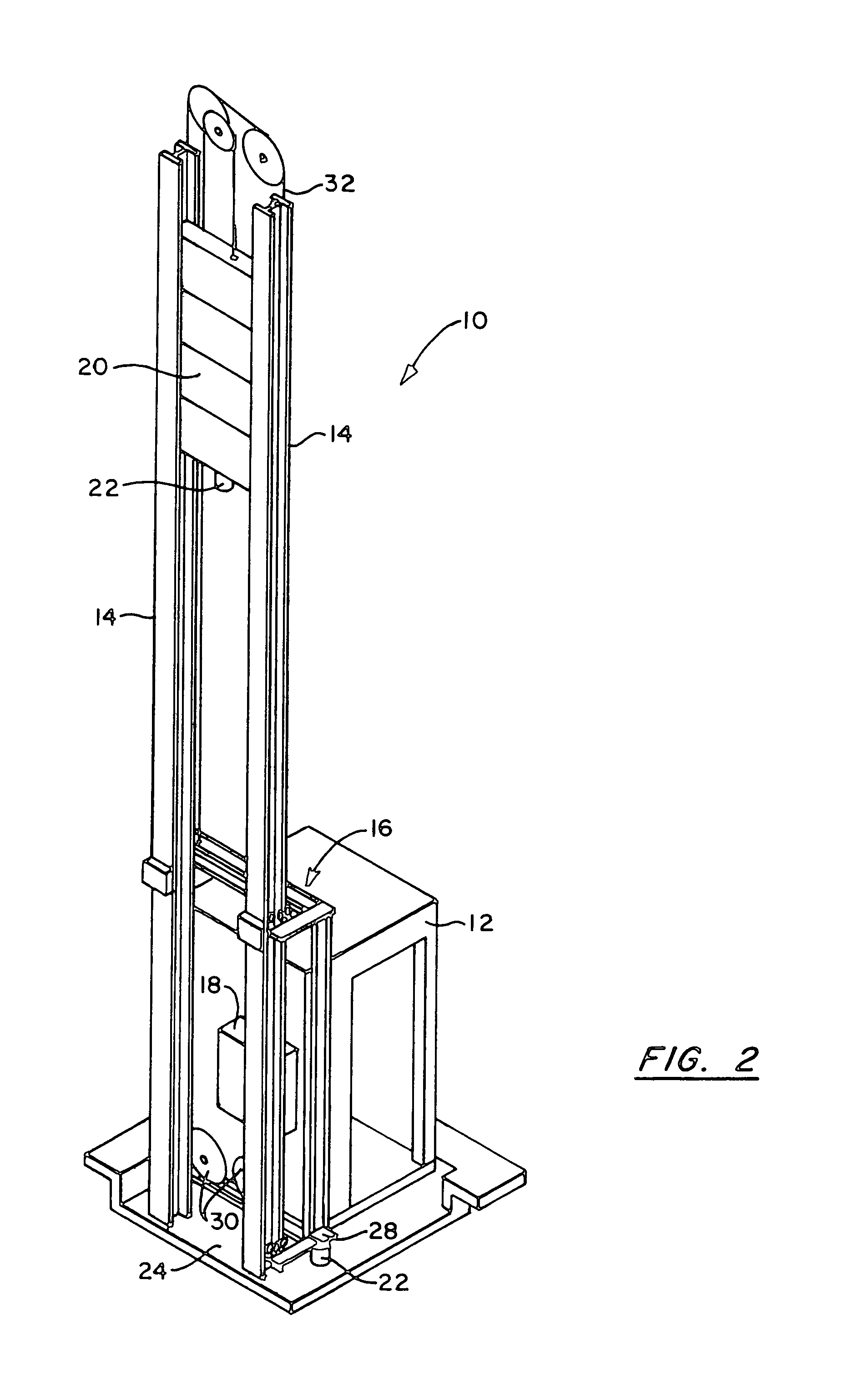
[0017]An elevator system 10 contains certain basic elements that are represented in the invention and illustrated in FIGS. 1 and 2. These elements include an elevator car 12 guided by at least one and preferably two guide rails 14 through the intermediary frame 16. The system 10 further includes a machine 18, shown as an on-board machine in the illustration but not limited as such, and several sheaves (discussed hereunder). A counterweight is illustrated as 20 and car buffers 22 are located on the floor 24 of the hoistway 26 in which car 12 is cycled, the buffers being placed outside of the area directly under the car 12 (also defined for purposes of this application as the elevator car footprint).

[0018]In order to achieve the desired beneficial result of the invention and provide a functioning elevator system without a pit, all of the conventional residents of the pit must be relocated to clearance spaces around the portion of hoistway 26 occupied by car 12. In a preferred embodime...


PUM


Abstract

A pitless elevator system removes a car buffer and machine, and other components where so equipped from under the elevator car such that the elevator car can be operated to a clearance between it and a floor of a hoistway of about three inches. The machine may be mounted on board the car or may be located elsewhere and the car buffer located in normal side clearance space. The system further provides a retractable toe guard to allow the car to bottom at the indicated distance from the floor. The system facilitates retrofit applications of elevators without the prior art drawback of digging a pit.

Description

[0001]This is a division of application Ser. No. 09 / 296,885 filed Apr. 22, 1999 now U.S. Pat. No. 6,095,288, the contents of which is incorporated herein by reference.BACKGROUND OF THE INVENTION[0002]1. Field of the Invention[0003]The invention relates to the elevator art. More particularly, the invention relates to an elevator system which is particularly conducive to retrofitability in structures without elevator pits as well as new construction where a pit is not desired or permitted.[0004]2. Prior Art[0005]In the elevator art it has been conventional for a very long period of time to build an elevator hoistway, i.e. the shaft in which an elevator car is moved upwardly and downwardly, with a pit. A pit is a continuation of the hoistway downwardly below the intended lowest level at which the elevator car will have duty. The lowest level may be a first floor or a basement, etc. Typically, a pit is about 4-5 feet in depth below the lowest elevator car level and thus requires a subst...

Claims


Application Information

Patent Timeline
Patent Type & Authority Patents(United States)
IPC IPC(8): B66B13/28B66B5/28B66B7/00B66B11/02B66B13/24
CPCB66B13/285B66B5/28B66B13/245
Inventor RIVERA, JAMES A.ST. PIERRE, BRUCESANSEVERO, FRANK M.
Owner OTIS ELEVATOR CO
Why Eureka
Try Eureka